
Traffic light system was one of the fascinating applications of Embedded systems and have been using the same till this day. I have previously posted a simple Traffic light system for one way roads with small timings check it out if you are interested in it. This is the four way traffic light system using embedded systems which was bit complex in nature as we need to consider the traffic flow in four different directions providing appropriate timings to each of the lights.
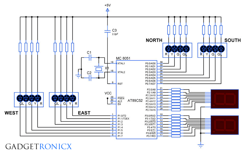
This system uses 8051 microcontroller ( AT89C52) , 7-segments and LED’s for indication. The LED’s which was used as lights was connected to the Microcontroller by means of common Anode configuration. In this configuration the Microcontroller was used to sink the current from the LED to its ports. That means logic 0 signal in the Microcontroller switches the LED ON and logic 1 signal switches the LED off. Here we are using 6 MHz crystal for the 8051 Microcontroller operation and you can use upto 12MHz crystal with this controller.
COMMON CATHODE 7-SEGMENT:

In this design, we are about to use a Common Cathode 7-segment in which the LED’s are connected in a manner sourcing from the Microcontroller. As you can see in the above pin configuration there is two common ground pins, we can use any one of it. The 7-segment should be connected to the port in the following order P2.0 to pin “a” of the 7 segment, P2.1 to b , P2.2 to c and ends up with P2.7 to h. These are the connection configurations and components we are going to use in this 4-way Traffic light system using 8051 Microcontroller.
DESIGN:

The above diagram illustrates the traffic flow layout of the four way road. And this is just a model of the four way road ,schemes and layout may subjected to change. I have chose this one for easier explanation of the traffic flow.
The traffic flow can be classified in to four phases in the above diagram and i have considered the North as starting point of this traffic flow. And in the above scheme vehicles are allowed to make a free right turn so we need to consider only two directions straight and left. So the green signal was classified into two types one for G for permitting vehicle to proceed forward and GL for permitting vehicles to left.
PHASE I-
- Initially Vehicle from A needs to travel to F and from E to B roads.
- So in the first Phase forward green signal in A and E permits vehicles to pass through while East and west roads are stopped by red signal.
PHASE II-
- Phase II permits the vehicle to pass from G to D and from C to H roads.
- Traffic flow from rest of the two roads North and south was stopped by means of Red signal.
PHASE III-
- Phase three permits traffic flow in the left directions from A to D and from E to H.
- Traffic flow in East and west are stopped by means of red signal.
PHASE IV-
- Phase four permits traffic flow from C to F and from G to B.
- Traffic flow in the North and south are stopped by means of red signal.
- The cycle repeats again from Phase I to Phase IV and thus the traffic is regulated.
NOTE:
The above scheme is just an example and are subjected to change in real time roads, as different four way traffic flow schemes are followed widely around the world. This illustration was aimed to make you understand the flow and guide in designing the system according to the flow of traffic.
TIMING OF THE SIGNALS:
The timing is one of the important factor to consider in a traffic light system. Here in this design i have programmed in such a way a red light will be on for 50 seconds and 10 seconds for Yellow light. So adding up a traffic flow or a Green signal will be On for 60 seconds totally before switching the flow to the next phase.
The 7 segment was used in this design to to display the timing to the vehicle users in the road. This ease up the vehicle users and provides knowledge of the timing left before the switching of the next signal.
PROGRAM OF TRAFFIC LIGHT SYSTEM:
The coding was done using Embedded C language using IDE 8051 software. The code was given below.
#include<stdio.h>
#include<reg51.h>
void delay(void);
void count1(void);
void count2(void);
sbit NR=P0^0; sbit NY=P0^1; sbit NG=P0^2; sbit NGL=P0^3; //Setting bit for LED's north
sbit SR=P0^4; sbit SY=P0^5; sbit SG=P0^6; sbit SGL=P0^7;   //Setting Bit for LED's South
sbit ER=P1^0; sbit EY=P1^1; sbit EG=P1^2; sbit EGL=P1^3;  //Setting Bit for LED's East
sbit WER=P1^4; sbit WEY=P1^5; sbit WEG=P1^6; sbit WEGL=P1^7; //Setting Bit for LED's West
unsigned char a[10]={0x06,0x5b,0x4f,0x66,0x6d,0x7d,0x07,0x7f,0x6f,0x3f}; //Array for displaying digits on segment 1,2.......9,0
unsigned char b[7]={0x3f,0x06,0x5b,0x4f,0x66,0x6d,0x7d}; //Array for displaying 0 to 6
unsigned int i,j,s,k;             //Assigning Integers
void main()                        //Main program
  {
     NR=1; NY=1; NG=0; NGL=1;       // I phase forward green for north lights
     SR=1; SY=1; SG=0; SGL=1;         // forward green for south lights
     ER=0; EY=1; EG=1; EGL=1;        //Red signal for east
     WER=0; WEY=1; WEG=1; WEGL=1;   //Red signal for west lights
      {
       count1();                            //Calling out subroutine to display digits in 7 segment
      }
     NR=1; NY=1; NG=0; NGL=1;     //I phase yellow signal
     SR=1; SY=1; SG=0; SGL=1;
     ER=1; EY=0; EG=1; EGL=1;
     WER=1; WEY=0; WEG=1; WEGL=1;
      {
       count2();                         //Calling out sub routine for displaying counts for yellow
      }
     NR=0; NY=1; NG=1; NGL=1;      //II phase red signal for north lights
     SR=0; SY=1; SG=1; SGL=1;
     ER=1; EY=1; EG=0; EGL=1;
     WER=1; WEY=1; WEG=0; WEGL=1;
      {
       count1();
      }
     NR=1; NY=0; NG=1; NGL=1;     //II phase yellow lights for North and south
     SR=1; SY=0; SG=1; SGL=1;
     ER=1; EY=1; EG=0; EGL=1;
     WER=1; WEY=1; WEG=0; WEGL=1;
       {
       count2();
       }
     NR=1; NY=1; NG=1; NGL=0;     //III phase Green left for north and south
     SR=1; SY=1; SG=1; SGL=0;
     ER=0; EY=1; EG=1; EGL=1;
     WER=0; WEY=1; WEG=1; WEGL=1;
       {
       count1();
       }
     NR=1; NY=1; NG=1; NGL=0;    //III phase yellow lights
     SR=1; SY=1; SG=1; SGL=0;
     ER=1; EY=0; EG=1; EGL=1;
     WER=1; WEY=0; WEG=1; WEGL=1;
     {
       count2();
       }
     NR=0; NY=1; NG=1; NGL=1;     //IV phase Red signal for North and south
     SR=0; SY=1; SG=1; SGL=1;
     ER=1; EY=1; EG=1; EGL=0;
     WER=1; WEY=1; WEG=1; WEGL=0;
     {
       count1();
       }
     NR=1; NY=0; NG=1; NGL=1;      //IV phase Yellow signal for north and south
     SR=1; SY=0; SG=1; SGL=1;
     ER=1; EY=1; EG=1; EGL=0;
     WER=1; WEY=1; WEG=1; WEGL=0;
     {
       count2();
       }
     }
  void count1(void)     //Sub routine for displaying numbers in segments for red signal
    {
   P2=0x3f;
    for(j=0;j<=4;)
      {
       for(i=0;i<=8;)
       {
        P3=a[i];
        i++;
        delay();
        }
       j++;
       P2=b[j];
       P3=0x3f;
       delay();
      }
    }
  void count2(void) //Sub routine for displaying numbers in segments for yellow signal
    {
      P2=0x3f;
      for(i=0;i<=8;)
        {
         P3=a[i];
         i++;
         delay();
        }
       P2=0x06;
       P3=0x3f;
       delay();
  }
  void delay(void)      //Sub routine for creating delay
    {
      for(s=0;s<=230;s++)     //Creating delay using number count
       {
         for(k=0;k<238;k++);
       }
    }
Modifying the array can extend your timings to different lights.
ROOM FOR MODIFICATIONS :
- Changing the lighting schemes or increasing the phases can be done by replacing the signal bits in the program.
- Additional lights for pedestrian can be added just by connecting LED’s parallel to the ports, MC capable of sinking currents of multiple LED’s.
- Array can be extended upto 90 seconds of timing.
I have also added the Proteus simulation file and hex file of this program below. Get the files here


Make the coding shorter
Plz tell me where to change the delay timings in program code.
Hi Tabish,
Its in the line 102 Void delay() sub routine. The code gives approximately 1 second not precisely
please send me the proteus files to ran_djc@hotmail.com i cant download it from this page.
can you plz send me the simulation of the 4 way traffic control system
please tel me the all values of the component and frequency of AT89C52 micro controller
Hello,,, have u got the values of missing components ???
C1 and C2 = 22pf and Resistors = 470 ohms
Crystal Frequency is 11.0592mhz
Thankyou for the code and the diagram, but the values of the C1, C2 and few resistors have not been mentioned can you please let me know about it?
C1 and C2 = 22pf and Resistors = 470 ohms
what is ur proteus version of this uploaded file ? plz hurry up 😀 and tnx for this schematic and code 🙂
Amka,
It was proteus version 7.7 🙂
This comment has been removed by the author.
Would you mind helping me out with the program and circuit diagram for controlling traffic light system using LDR? –
I guess you are talking about controlling the light sequence based on LDR’s input (Day or night). It is possible with 8051 but you got to add a special ADC chip along with 8051 since it lacks the inbuilt ADC module within it. Or you may use PIC or AVR series microcontrollers which will do a great job.
can you modify it to density based traffic control using IR sensor n removing display plz ?
Actually many visitors asking for this density based traffic light, but iam not sure that it can be implemented using IR sensor. I will Try my best
hope u succeed very soon
Do you have such four way traffic light circuit in which we can add direct delay to RED & GREEN using keypad No need of 7 Segment Display….. jus system should ask timing for different RED & Green on LCD display
Using keypad to offer delay input is a tedious process. However you could alter it by using two buttons one to increment the delay and other to decrement it. This should make your task easier
can u forward code to logontokeerthi11@gmail.com