DIY Arduino based lockers can be found plenty in the internet where keypad was used to feed lock input. But this Bluetooth enabled Door locker uses Bluetooth as a medium to connect with the locker and your smart phone to feed input credentials. This locker allows you to lock/unlock your locker without physical touch when you are within the range of Bluetooth communication.
DESIGN:
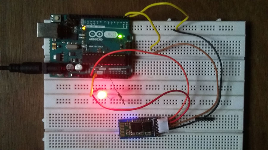
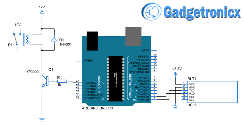
Arduino is the heart of this locker system and HC-05 module provides the bluetooth connectivity for the arduino. I have added a relay to act as an activator for the E-locker in the above design. You may replace it with any other electronic activator or door activator if you are going to use it for doors. If that’s the case alter the design in such a way that the system is provided with enough power to drive the activator. I have added a simple LED in the project i have built-in place of Relay since i haven’t got one to use, kindly excuse me for that.
HC-05:
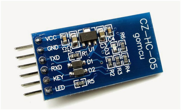
The HC-05 is a pretty famous Bluetooth module used in standard embedded applications where BT connectivity is required. This module converts the data received through Bluetooth and converts it into serial format that can be understood by Controllers equipped with UART communication. This module should be powered by +3.3v and special key pin for secured communication.
BT TERMINAL SOFTWARE:
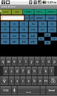
A special software known as Bluetooth serial terminal is needed for this project. This software is used to send raw data from our device to the HC-05 module connected to the Arduino. This kind of software available for all smart phone platforms such as Android, iOS and Windows. I have used SENA BTerm software Android for this project. However you can choose any Bluetooth terminal software in any platform, everything will work just fine.
FEATURES:
The locker password can be set to any complex level and length with no restrictions.
Bluetooth access reduces the hardware size and complexity of adding keypad to the system.
Wireless activation of door locker will be the most highlighting specs of this system.
Less power consumption by Bluetooth will be of great advantage.
Initialize the serial communication in your Arduino.
Send the Enter password prompt message via Bluetooth to the terminal.
When serial interrupt occurs, fetch the data from the receiving buffer of Arduino.
Look for the password match between user entered string via BT and predefined password.
If match occurs send unlocked message and activate the door activator, if not send an error message and enter password message after few seconds.
If the lock is opened look for serial interrupt and check for the single character command entered via BT terminal.
If “L” command was entered turn off the activator, if a wrong command was entered send an error message to BT terminal.
CODE:
char inbyte;
String pwd="frank";               //Predefined password
String inpt="";
boolean lock_enable=true;        //Flag to check lock status

void setup() {
Serial.begin(9600);             //Enabling serial communication
pinMode(A0, OUTPUT);            //Pin to activate the door
Serial.println("ENTER PASSWORD");
}

void loop() {
    if(lock_enable==true)          //Activator infinite loop
    digitalWrite(A0, LOW);
    else if(lock_enable==false)
    digitalWrite(A0, HIGH);
            }


void serialEvent()                   //Checking for serial interrupt
{
  while(Serial.available())         //Repeat till bytes are available in buffer
  {
    inbyte=(char)Serial.read();     //Char reading
    delay(200);
    inpt=inpt+inbyte;              //Changing the input character into a string
    inbyte='\n';
  }
  check();                         //Run the password check routine
}

void check()
{
switch(lock_enable)
  {
  case true:                     //If the lock is enabled/locked
    {
    if(inpt==pwd)                //Check for password match
        {
          lock_enable=false;
          Serial.println(inpt);
          inpt="";
          Serial.println("UNLOCKED");   //Display unlocked message
        }
       else if(inpt!=pwd)
       {
          Serial.println(inpt);
          inpt="";
          Serial.println("WRONG PASSWORD");  //Display error message
          delay(2000);
          Serial.println("ENTER PASSWORD");  //Prompt to enter password again
          delay(100);
       }
       break;
     }

  case false:                         //If lock is not enabled/opened
    {
    if(inpt=="L")                    //Check for lock command
     {
     lock_enable=true;               //Change the flag and lock the door
     inpt="";
     Serial.println("LOCKED");
     delay(2000);
     Serial.println("ENTER PASSWORD");
     }
    else
     {
     inpt="";
     Serial.println("UNKNOWN COMMAND");   //Wrong command
     }
     break;
    }
}
}
NOTE:
I have added a red LED in my built project instead of relay for indication, do not get confused.
You can add a different activator other than the relay provided the altered design to provide enough power for the activator .
HI Frank
Is it possible for this system to be used to control more than one locker? We want to use this to control 20 lockers using one system. Is that possible?
Hi Nick,
You can use multiple locker activators since all you need to do is add a transistor and relay to digital pins of Arduino and activate them accordingly in your code.
This project coud also work without arduino at all! How? Bluetooth module have ITS own access control, autentication on devices pairing,by 4-digits or more. So, if ANY serial data is outgoing from BT Tx pin (low state or state changing), it meaans devices are already connected and paired. Right, 4-digit code isnt very secure, but 5-letter password shown in listing isnt too. Just like code-padlock
Hi, you have used the command “lcd.setCursor(0,1);” in the check-routine.
When i load this in the UNO and precompile the code, i get the message “lcd is not declared in this scope”
What can i do?
For those of us that learn by hacking/building on people like Frank’s work (thank you so much Frank!), could someone please add a layer to this project and show the audience how to make an Android app with a single button to make Franks project work without needing to use Bterm?
Oregoner,
Thank you so much. Unfortunately i don’t have any idea on Android app development to do so. If anyone comes up with such great thing i am glad to add to this article with attribution.


HI Frank
Is it possible for this system to be used to control more than one locker? We want to use this to control 20 lockers using one system. Is that possible?
Hi Nick,
You can use multiple locker activators since all you need to do is add a transistor and relay to digital pins of Arduino and activate them accordingly in your code.
This project coud also work without arduino at all! How? Bluetooth module have ITS own access control, autentication on devices pairing,by 4-digits or more. So, if ANY serial data is outgoing from BT Tx pin (low state or state changing), it meaans devices are already connected and paired. Right, 4-digit code isnt very secure, but 5-letter password shown in listing isnt too. Just like code-padlock
Hi, you have used the command “lcd.setCursor(0,1);” in the check-routine.
When i load this in the UNO and precompile the code, i get the message “lcd is not declared in this scope”
What can i do?
Febra,
Apologize for the error, LCD was not needed in this project. That line was added by mistake. Now the code was updated
For those of us that learn by hacking/building on people like Frank’s work (thank you so much Frank!), could someone please add a layer to this project and show the audience how to make an Android app with a single button to make Franks project work without needing to use Bterm?
Oregoner,
Thank you so much. Unfortunately i don’t have any idea on Android app development to do so. If anyone comes up with such great thing i am glad to add to this article with attribution.