HT12E is a 2^12 series encoder IC widely used in remote control and very common among Radio Frequency RF applications. This HT12E IC capable of converting 12 bit Parallel data inputs into serial outputs. These bits are classified into 8 (A0-A7) address bits and 4(AD0-AD3) data bits. Using the address pins we can provide 8 bit security code for secured data transmission between the encoder and the decoder. The encoder and decoder should use the same address and data format. HT12E is capable of operating in a wide Voltage range from 2.4V to 12V and also consists of a built in oscillator. Let’s move into the working of HT12E encoder IC.
PIN DESCRIPTION OF IC HT12E:
The pin Description of the IC HT12E was pretty simple to understand with total of 18 pins.
VDD and VSS: Positive and negative power supply pins.
OSC1 and OSC2: Input and output pins of the internal oscillator present inside the IC.
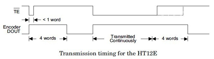
TE: This pin is used for enabling the transmission, a low signal in this pin will enable the transmission of data bits.
A0 – A7: These are the input address pins used for secured transmission of this data. These pins can be connected to VSS for low signal or left open for high state.
AD0 – AD3: This pins are feeding data into the the IC. These pins may be connected to VSS for sending LOW since it is a active low pin
DOUT: The output of the encoder can be obtained through this pin and can be connected to the RF transmitter.
WORKING OF HT12E IC:
HT12E starts working with a low signal on the TE pin. After receiving a low signal the HT12E starts the transmission of 4 data bits as shown in the timing diagram above. And the output cycle will repeats based on the status of the TE pin in the IC. If the TE pin retains the low signal the cycle repeats as long as the low signal in the TE pin exists. The encoder IC will be in standby mode if the TE pin is disabled and thus the status of this pin was necessary for encoding process. The address of these bits can be set through A0 – A7 and the same scheme should be used in decoders to retrieve the signal bits.
PRACTICAL CIRCUIT USING HT12E:
Practical Application Circuit
The above diagram shows the practical set up of the HT12E encoder IC for better understanding on the working.
Hi frank
thank you for time
i have problem with my project when i made saparate two bread board using arduino UNO by using ( RF Tx 433Mhz and Rx 433Mhz ) as wireless, then i wrote a code for arduino at least 10 line program then i used two IC HT12E for Tx and HT12D for Rx.
my equation are:
is the two ICs need a code?
please help me about that project
thanks…
Hii Frank, I am interfacing 4 encoder with different address configuration.. In ht12d decoder section, i am changing the address by giving delay. But now, if i want to connect more than 4 encoder how do i configure data pins? I know i can give 2^7 different address. But if i want to transmit data in 5th encoder, in which pin of encoder sholud i provide data to encoder???
SSS,
As per the datasheet you need that resistor to kick start the internal oscillator in the chip which in turn feeds clock pulse to data transmission
Dear Frank Donald
I appreciate your clear explanation of the HT12D & E working and using it for RF 433 Mhz transmission. I planning for dynamic addressing the HT12D and HT12E Ics by connecting the ULN 2803 output pins to the address pins of Encoder and Decoder ICs and control the address by Microcontroller. Will this work?
Gunasekaran,
Am not sure about what you are asking. ULN2803 was a transistor array IC used for driving high power devices. There is no use of that IC here. Regarding the addressing you can use a simple switch to feed your desired address. Hope it is clear now
Thank you for your reply.
The query I raised about is dynamic addressing i.e. the pin numbers (1 to 8) of IC HT12D or HT12E connected to pin number 18 to 10 of ULN 2803. Now by controlling pin numbers 1 to 8 of ULN 2803 by sending HIGH from Microcontroller we get LOW on corresponding pins address input pins of HT12D or HT12E. No mechanical switching involved. Control the encoding / Decoding by Microcontroller thereby resulting in dynamic address setting for transmission and receiver.
Gunasekaran,
I presume you want to use ULN2803 in between a controller and HT12E for the sake of logic shifting? HT series IC’s are CMOS type so supplying 5v to these IC’s must enable you to feed logic directly from MCU to these IC’s. Hope am clear
Thank you for the reply and clarification.
As advised by you I can directly connect 8 pins of MCU to HT12E but I want isolation from VCC of HT12E from MCP VCC hence I plan to switch On/OFF the address pins through ULN2803.
Thank you and I will let you know the working of the circuit.
Kind of. The differences between both is that the HT12E words, don’t have the 0101 at the end. So there’s no way to filter signals coming from other sources.
Sir, i made the address bit as 0 and data as 1000 then the transmitted data is
syn.bit 0 0 0 0 0 0 0 0 1 0 0 0 am i right. Then what about the syn.bit.
According to the Datasheet, the Fosc depends on the value of the resistor connected between the 15th and 16th pins. And the VPP, of course, which is usually about 1M5. So the frequencies are between the 1.5KHz and 2KHz.


 HT12E starts working with a low signal on the TE pin. After receiving a low signal the HT12E starts the transmission of 4 data bits as shown in the timing diagram above. And the output cycle will repeats based on the status of the TE pin in the IC. If the TE pin retains the low signal the cycle repeats as long as the low signal in the TE pin exists. The encoder IC will be in standby mode if the TE pin is disabled and thus the status of this pin was necessary for encoding process. The address of these bits can be set through A0 – A7 and the same scheme should be used in decoders to retrieve the signal bits.
 RF Remote control circuit")
 RF Remote control circuit")
 car at home")

")


Hi frank
thank you for time
i have problem with my project when i made saparate two bread board using arduino UNO by using ( RF Tx 433Mhz and Rx 433Mhz ) as wireless, then i wrote a code for arduino at least 10 line program then i used two IC HT12E for Tx and HT12D for Rx.
my equation are:
is the two ICs need a code?
please help me about that project
thanks…
Abdullah,
No the HT12E and HT12D are encoder chips not programming ones. So you can connect your Arduino with it and work.
Hii Frank, I am interfacing 4 encoder with different address configuration.. In ht12d decoder section, i am changing the address by giving delay. But now, if i want to connect more than 4 encoder how do i configure data pins? I know i can give 2^7 different address. But if i want to transmit data in 5th encoder, in which pin of encoder sholud i provide data to encoder???
I have a doubt. Why do we put a resistor between two pins of oscillator viz.pin 15 n 16 in ht12e
SSS,
As per the datasheet you need that resistor to kick start the internal oscillator in the chip which in turn feeds clock pulse to data transmission
Dear Frank Donald
I appreciate your clear explanation of the HT12D & E working and using it for RF 433 Mhz transmission. I planning for dynamic addressing the HT12D and HT12E Ics by connecting the ULN 2803 output pins to the address pins of Encoder and Decoder ICs and control the address by Microcontroller. Will this work?
Request you idea on this.
Gunasekaran,
Am not sure about what you are asking. ULN2803 was a transistor array IC used for driving high power devices. There is no use of that IC here. Regarding the addressing you can use a simple switch to feed your desired address. Hope it is clear now
Dear Frank
Thank you for your reply.
The query I raised about is dynamic addressing i.e. the pin numbers (1 to 8) of IC HT12D or HT12E connected to pin number 18 to 10 of ULN 2803. Now by controlling pin numbers 1 to 8 of ULN 2803 by sending HIGH from Microcontroller we get LOW on corresponding pins address input pins of HT12D or HT12E. No mechanical switching involved. Control the encoding / Decoding by Microcontroller thereby resulting in dynamic address setting for transmission and receiver.
Gunasekaran,
I presume you want to use ULN2803 in between a controller and HT12E for the sake of logic shifting? HT series IC’s are CMOS type so supplying 5v to these IC’s must enable you to feed logic directly from MCU to these IC’s. Hope am clear
Dear Frank Donald,
Thank you for the reply and clarification.
As advised by you I can directly connect 8 pins of MCU to HT12E but I want isolation from VCC of HT12E from MCP VCC hence I plan to switch On/OFF the address pins through ULN2803.
Thank you and I will let you know the working of the circuit.
So this IC encoding type is kind of OTP encoding, right?
Kind of. The differences between both is that the HT12E words, don’t have the 0101 at the end. So there’s no way to filter signals coming from other sources.
Unk,
Your address should be unique and only know to your receiver end to avoid other source signal interference
I know. But There’s A LOT of interference here. I guess it could be the WiFi router that is at 50″ of distance from the RX I made.
What do they mean with “4 words”? They said that this encoder “sends 4 words” every time NOT(TE) is grounded.
sir,which algorithm used in this encoder ic ?
Girish,
Not sure haven’t mentioned any in datasheet
Sir, i made the address bit as 0 and data as 1000 then the transmitted data is
syn.bit 0 0 0 0 0 0 0 0 1 0 0 0 am i right. Then what about the syn.bit.
Hi Saran,
There is no special sync bits used. Its sync circuit forms a building block of this IC . Refer page 8 of the datasheet for further clarifications
http://www.botskool.com/downloads/electronics/datasheets/HT12E.pdf
Sir, which type of encoding technique is used in HT12E?
What is the frequency of the Serial Data Produced at the OUTPUT pin of the HT12E IC
Kartik,
That’s an interesting question. Datasheet have specified the output frequency of HT12A to be around 38khz. But no such details available for HT12E.
According to the Datasheet, the Fosc depends on the value of the resistor connected between the 15th and 16th pins. And the VPP, of course, which is usually about 1M5. So the frequencies are between the 1.5KHz and 2KHz.
What will be the output of Dout of HT12E if the input signal is from ARM CONTROLLER?
Santhosh,
The HT12E input pins take logic 1 or 0 it doesn’t matter whether it comes from a controller or any other logic devices.