HT12E is a 2^12 series encoder IC widely used in remote control and very common among Radio Frequency RF applications. This HT12E IC capable of converting 12 bit Parallel data inputs into serial outputs. These bits are classified into 8 (A0-A7) address bits and 4(AD0-AD3) data bits. Using the address pins we can provide 8 bit security code for secured data transmission between the encoder and the decoder. The encoder and decoder should use the same address and data format. HT12E is capable of operating in a wide Voltage range from 2.4V to 12V and also consists of a built in oscillator. Let’s move into the working of HT12E encoder IC.
PIN DESCRIPTION OF IC HT12E:
The pin Description of the IC HT12E was pretty simple to understand with total of 18 pins.
VDD and VSS: Positive and negative power supply pins.
OSC1 and OSC2: Input and output pins of the internal oscillator present inside the IC.
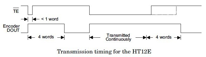
TE: This pin is used for enabling the transmission, a low signal in this pin will enable the transmission of data bits.
A0 – A7: These are the input address pins used for secured transmission of this data. These pins can be connected to VSS for low signal or left open for high state.
AD0 – AD3: This pins are feeding data into the the IC. These pins may be connected to VSS for sending LOW since it is a active low pin
DOUT: The output of the encoder can be obtained through this pin and can be connected to the RF transmitter.
WORKING OF HT12E IC:
HT12E starts working with a low signal on the TE pin. After receiving a low signal the HT12E starts the transmission of 4 data bits as shown in the timing diagram above. And the output cycle will repeats based on the status of the TE pin in the IC. If the TE pin retains the low signal the cycle repeats as long as the low signal in the TE pin exists. The encoder IC will be in standby mode if the TE pin is disabled and thus the status of this pin was necessary for encoding process. The address of these bits can be set through A0 – A7 and the same scheme should be used in decoders to retrieve the signal bits.
PRACTICAL CIRCUIT USING HT12E:
Practical Application Circuit
The above diagram shows the practical set up of the HT12E encoder IC for better understanding on the working.
how many data pins we can give data into ht12e. & why A0-A& pins are used
and i wanna build a 20 channel transmitter so please guide by giving some iinnfo or helpful links
Jatin,
Please read the above explanation carefully, there are only 4 data pins AD0 to AD3 and address pins are from A0 to A7. That’s 8 bits dedicated for channels so you can make up to 256 channels using this chip 🙂
Hi Yesha,
Answered this question below. Quoting from them
“This chip consists of an inbuilt oscillator (Feeds pulses for the chip to operate). And in the datasheet it was specified you need to connect the pin OSC1 and OSC2 with a resistor for functioning of oscillator.”
sir, from where can i get the whole kit of 433 mhz transmitter receiver.
please send me on nikhilsingh22895@gmail.com
I WANT THE WHOLE KIT WITH CONNECTION DIAGRAM AND ALL COMPONENTS.
I WILL BUY IT FOR ANY COST.
OR A READY MADE VERSION OF 433 MHZ RUNNING KIT WILL ALSO DO.
Shailesh,
This chip consists of an inbuilt oscillator (Feeds pulses for the chip to operate). And in the datasheet it was specified you need to connect the pin OSC1 and OSC2 with a resistor for functioning of oscillator.
by default, if i do not give ground to data pins, then 1 is the output from the data output. That means this Ic provides some voltage which i found to be 0.24V by default at its data pins. And we are actually making the data input pins 0 by connecting them to ground using the switch. Am i right??
Swanpil,
Well not exactly HT12E data input pins are active low which means giving low or ground signal will be taken as logic 1 whereas leaving them floating will be taken as logic 0.Sometimes we may face problem when leaving pins floating a simple solution will be adding a pull up resistor to the data input pins. This will assure logic 0 except when switch is closed. I hope this explanation helps.
Biswajit,
I believe you have to perform some tweaks to do it so. In the above IC only 4 bit data that is nibble is possible to send at a time. So in order get a 8 bit data you can split the 8 bit data in to two nibbles and send it separately. Later you can combine those two nibbles in the receiver end as a byte. This can be done by using a controller in the receiver end and programming it accordingly. Hope this suggestion helps you, if something better turns up do post it here. Cheers
do we need different resister values(Rosc) for different transmitter frequencies (i.e 433mhz and 315mhz).
i have a encoder decoder module which is working fine with 433mhz but showing no response for 315mhz tx rx.
looking forward for your reply 🙂
Kush,
Well i don’t think so. As far i aware 433Mhz module modulates the incoming digital signal using ASK technique and then transmits it. Am not sure about 315 mhz module though but i believe that the Oscillator frequency of the encoder and the decoder shouldn’t be the factor for not functioning. Well its to observe this rule and make sure you have implemented this rule while designing your project
The recommended oscillator frequency is fOSCD (decoder)= 50 fOSCE (HT12E encoder)
= 1/3fOSCE (HT12A encoder)
Narashiman, The HT12E uses a RC oscillator to generate the required frequency. Capacitor is built inside whose value is unknown, the external resistor we are going to use forms the RC oscillator. If you go through the datasheet you can find a graph ” Frequency vs Supply voltage” which gives the value of resistors to be used to generate required frequency. View the Graph in this link .Hope it helps, let me know if you need further clarification.


 HT12E starts working with a low signal on the TE pin. After receiving a low signal the HT12E starts the transmission of 4 data bits as shown in the timing diagram above. And the output cycle will repeats based on the status of the TE pin in the IC. If the TE pin retains the low signal the cycle repeats as long as the low signal in the TE pin exists. The encoder IC will be in standby mode if the TE pin is disabled and thus the status of this pin was necessary for encoding process. The address of these bits can be set through A0 – A7 and the same scheme should be used in decoders to retrieve the signal bits.
 RF Remote control circuit")
 RF Remote control circuit")
 car at home")

")


how many data pins we can give data into ht12e. & why A0-A& pins are used
and i wanna build a 20 channel transmitter so please guide by giving some iinnfo or helpful links
Jatin,
Please read the above explanation carefully, there are only 4 data pins AD0 to AD3 and address pins are from A0 to A7. That’s 8 bits dedicated for channels so you can make up to 256 channels using this chip 🙂
what is the value of resistor connected to pin 16 of HT12E?
how can we deside that value?
Hi Yesha,
Answered this question below. Quoting from them
“This chip consists of an inbuilt oscillator (Feeds pulses for the chip to operate). And in the datasheet it was specified you need to connect the pin OSC1 and OSC2 with a resistor for functioning of oscillator.”
sir, from where can i get the whole kit of 433 mhz transmitter receiver.
please send me on nikhilsingh22895@gmail.com
I WANT THE WHOLE KIT WITH CONNECTION DIAGRAM AND ALL COMPONENTS.
I WILL BUY IT FOR ANY COST.
OR A READY MADE VERSION OF 433 MHZ RUNNING KIT WILL ALSO DO.
Hi Nikhil,
There of lots of these modules available online. Here is one from Amazon.in
http://www.amazon.in/433Mhz-Wireless-Transmitter-Receiver-Module/dp/B00NRQ3BIM?tag=googinhydr18418-21&tag=googinkenshoo-21&ascsubtag=8e2c7c51-d441-45ea-9c1b-46c24f92b4db
Hope it helps.
What is the necessary of the OSC1 and OSC2 in the encoder and decoder fort transmission of the data
Shailesh,
This chip consists of an inbuilt oscillator (Feeds pulses for the chip to operate). And in the datasheet it was specified you need to connect the pin OSC1 and OSC2 with a resistor for functioning of oscillator.
Hope i made it clear, thanks!
What is the necessary of the OSC1 and OSC2 in the encoder and decoder fort transmission of the data
by default, if i do not give ground to data pins, then 1 is the output from the data output. That means this Ic provides some voltage which i found to be 0.24V by default at its data pins. And we are actually making the data input pins 0 by connecting them to ground using the switch. Am i right??
Swanpil,
Well not exactly HT12E data input pins are active low which means giving low or ground signal will be taken as logic 1 whereas leaving them floating will be taken as logic 0.Sometimes we may face problem when leaving pins floating a simple solution will be adding a pull up resistor to the data input pins. This will assure logic 0 except when switch is closed. I hope this explanation helps.
why we are use 434 Mhz frequency in patient monitoring system
Rajesh,
Patient monitoring system? can’t get your point. Please be specific and clear with your question.
Hi. If the address is different on the decoder then it can’t receive the data or ?
Colin,
Yes, you cannot receive the data if you use a different address in the decoder.
how to send 8bit data through this IC,do you have any idea?
Biswajit,
I believe you have to perform some tweaks to do it so. In the above IC only 4 bit data that is nibble is possible to send at a time. So in order get a 8 bit data you can split the 8 bit data in to two nibbles and send it separately. Later you can combine those two nibbles in the receiver end as a byte. This can be done by using a controller in the receiver end and programming it accordingly. Hope this suggestion helps you, if something better turns up do post it here. Cheers
do we need different resister values(Rosc) for different transmitter frequencies (i.e 433mhz and 315mhz).
i have a encoder decoder module which is working fine with 433mhz but showing no response for 315mhz tx rx.
looking forward for your reply 🙂
Kush,
Well i don’t think so. As far i aware 433Mhz module modulates the incoming digital signal using ASK technique and then transmits it. Am not sure about 315 mhz module though but i believe that the Oscillator frequency of the encoder and the decoder shouldn’t be the factor for not functioning. Well its to observe this rule and make sure you have implemented this rule while designing your project
The recommended oscillator frequency is fOSCD (decoder)= 50 fOSCE (HT12E encoder)
= 1/3fOSCE (HT12A encoder)
Hope it helps.
Sir, how to build quadcopter I
Hi Ujjwal,
This link might help you
http://www.instructables.com/id/DIY-Quadcopter/
How to find Rosc for a specified baud rate or frequency ?
Narashiman,
The HT12E uses a RC oscillator to generate the required frequency. Capacitor is built inside whose value is unknown, the external resistor we are going to use forms the RC oscillator. If you go through the datasheet you can find a graph ” Frequency vs Supply voltage” which gives the value of resistors to be used to generate required frequency. View the Graph in this link .Hope it helps, let me know if you need further clarification.
How can I interface this if ht12e with 8051….pllzzzz….can u help me???