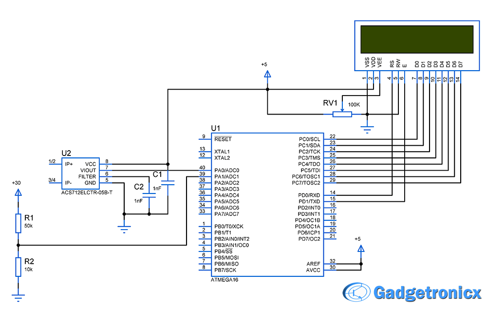
Voltage and current are two most important parameters of electricity. This project teaches you to build a simple volt-amp meter using avr microcontroller. This project may not enable you to build a high end measurement tool but will be a good diy project which gives a better understanding on A/D converter in microcontrollers. This meter is capable of measuring voltage ranging from 0 to 30V and current ranging from 0 to 5A. Care must be taken while using so that the input should not exceed the specifications.
SETTING UP THE SENSORS:
VOLTAGE MEASUREMENT:
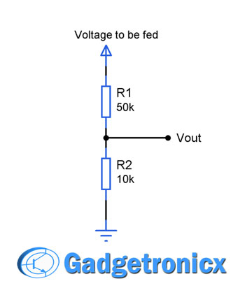
A simple potential divider is employed to measure the voltage. The above potential divider was set up in such a way it gives 5v as output when 30v input is applied to it since the input voltage given to AVR should be less than or equal to 5V.
The formula for setting the potential divider resistor is
Vout = Vin x R2 / (R1 + R2)
We knew our Vout should be <= 5V. So applying this and fixing a resistor R2 as 10k will give
5v = 30 x 10k /(R1 + 10k)
R1 = 50k.
CURRENT MEASUREMENT:
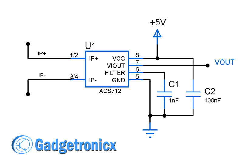
We are using a pretty straight forward approach to measure current. Here we are using a Hall effect current sensor to measure current. This sensor can measure current up to 5A. 1A of current is equivalent to 185mv of change in output voltage. There are also 20A and 30A version of this chip available. Read more about this sensor here.
CALIBRATION:
The next task is to perform the calibration to display the real values using our Microcontroller. So in order to do that we need to know the Step Size of our A/D converter in AVR microcontroller. It was given by the formula
Step size = Vref / 2^10 (Since it is a 10 bit ADC) .
= 5/1024 = 4.88mv
This is the step size of our A/D converter in AVR microcontroller that is for every 4.88mv change in input there will be a change in ADC value in the register.
TO CALCULATE VOLTAGE:
As i have previously mentioned the voltage sensing is done by using a Voltage divider which bears the formula
Vout = Vin x R2 / (R1 + R2)
Am going to use this formula to derive the real voltage from the sensed voltage. Since we obtain the sensed voltage in the form of digital numbers we need to make a conversion to obtain Vout value from it. So
Vout = Digital Value read from A/D register * Vref / 2^10
Vout = Digital Value read from A/D register * 5 / 1024 , Simplifying this we get
Vout = Digital Value * 0.00488
This will give us exact Vout voltage from the voltage divider, now applying this Vout in the divider equation will give the real voltage given as input to the voltage divider.
Vin= Vout * (R1+R2) /R2
Vin = Vout * 60k / 10K
Vin = Vout * 6
The above final equation i have added in the 41 line of the code, This will give the real voltage that needs to be measured and displayed.
TO CALCULATE CURRENT:
The IC ACS712 5A chip gives out 185mA of voltage change in the output when there is a 1A change in the current flow. And the nominal voltage will be of 2.5 Volts so the ADC always reads 2.5 V even if there is no current through it.
Vout = Digital value read from the A/D register * 5 /1024 , simplifying we get
Vout = Digital value * 0.00488
So the real value of current can be given as
Amp = (Vout – Nominal Voltage) / 185mA (Change in output voltage of sensor)
Amp = (Vout – 2.5) / 0.185
This equation was added in the line 54 of the code. I have replaced Amp with available float variable Vin in the code to cut down the code size.
CODE:
#include<avr/io.h>
#define F_CPU 8000000UL
#include<util/delay.h>
#include<stdio.h>
double vin;
double vout;
unsigned int value;
char output[6];

void lcd_cmd(char cmd)              //Command sub routine LCD
{
   PORTC=cmd;
   PORTD&=~(1<<0);
   PORTD|=(1<<1);
   _delay_ms(5);
   PORTD&=~(1<<1);
   _delay_ms(5);
}

void lcd_data(char *txt)         //Data sub routine LCD
{
   while(*txt!='\0')
   {
   PORTC=*txt;
   PORTD|=(1<<0);
   PORTD|=(1<<1);
   _delay_ms(5);
   PORTD&=~(1<<1);
   _delay_ms(5);
   txt++;
    }
}

void voltage(void)             //Sub routine to read voltage
{
  ADMUX|=(1<<0);
  ADCSRA|=(1<<6);
  while(ADIF==0);
  value=ADCL|ADCH<<8;
  vout=value*0.00488;             //To determine output Voltage from sensor
  vin=6*vout;                    //To determine real voltage
  sprintf(output,"%.2f",vin);
  lcd_cmd(0x86);
  lcd_data(output);
}

void current(void)
{
  ADMUX&=~(1<<0);
  ADCSRA|=(1<<6);
  while(ADIF==0);
  value=ADCL|ADCH<<8;
  vout=value*0.00488;            //To determine output voltage from sensor
  vin=(vout-2.5)/0.185;          //To determine real current
  sprintf(output,"%.2f",vin);    //Float to char conversion for printing
  lcd_cmd(0xc6);
  lcd_data(output);
}

int main(void)
{
  DDRC=0xff;
  DDRD=0x03;
  PORTC=0x00;
  PORTD=0x00;
  lcd_cmd(0x38);
  lcd_cmd(0x01);
  lcd_cmd(0x0c);
  lcd_cmd(0x80);
  lcd_data("VOLTS:");
  lcd_cmd(0xc0);
  lcd_data("CURNT:");
  ADMUX=0x00;
  ADCSRA=0x87;                     //Initializing A/D converter
  while(1)
   {
    voltage();            //Voltage display
    _delay_ms(10);
    current();           //Current Display
   }
  return 0;
}
Hi Ankit,
I have observed some of other readers has faced similar issue. I think this might because of improper decimal to char conversion ( a rough guess ). Have you declared the header file in your code ?
Also do tell me if there is just question mark displayed in the output or its a combination of other gibberish characters ?
I have attempted this exact circuit multiple times now. One time I even added in the suggested delay in the comments and still I am getting no output from the LCD screen. Could you please review your code to make sure it is functional or could I be missing something that possibly wasn’t in the schematic. Would the LCD model # matter. I am using a 16×2 lcd and I have tested with different LCD screens which all work fine otherwise.
Hello
I am new to Microcontrollers
i simulate your project in winAVR and codevision and proteus but only showing
VOLTS:?
CURENT:?
maybe help to solve its problem ?
Thanks Hassan
Hassan,
Well the simulations cannot be totally trusted. I would suggest you to build this actual circuit. It should work since the code and circuit is tested.
Your code has a little problem that will ruin the whole result.
I have figured it out after simulating your circuit in Proteus 8.
There is a 10ms delay needed after setting the ADSC bit in ADSRA both in voltage and current function. [after ADCSRA|=(1<<6); line]
Otherwise the code didn't show the desired values on LCD.
Hi Ali,
Thanks for the suggestion. But I guess the delay is not really necessary since once the ADSC bit is activated the code waits for the interrupt flag to be raised which indicates the AD conversion. Have you tried this out in real time ?

 We are using a pretty straight forward approach to measure current. Here we are using a Hall effect current sensor to measure current. This sensor can measure current up to 5A. 1A of current is equivalent to 185mv of change in output voltage. There are also 20A and 30A version of this chip available. Read more about this sensor here.


 Microcontroller")


Hi, what fuses did you use, because i dont want to lock my atmega 😀 thanks,
Hello, my professor asked me to convert this c code into assembly language but I dont know how to do it, can you please help meee. :((
Getting output as volt ?
current ?
please help me to solve this problems.
thanks for the post.
Hi Ankit, in your code ?
I have observed some of other readers has faced similar issue. I think this might because of improper decimal to char conversion ( a rough guess ). Have you declared the header file
Also do tell me if there is just question mark displayed in the output or its a combination of other gibberish characters ?
Yes sir, Output coming as question mark
I have attempted this exact circuit multiple times now. One time I even added in the suggested delay in the comments and still I am getting no output from the LCD screen. Could you please review your code to make sure it is functional or could I be missing something that possibly wasn’t in the schematic. Would the LCD model # matter. I am using a 16×2 lcd and I have tested with different LCD screens which all work fine otherwise.
Hi Jackal,
Do you see any gibberish message across your LCD screen or its just blank ?
Hello
I am new to Microcontrollers
i simulate your project in winAVR and codevision and proteus but only showing
VOLTS:?
CURENT:?
maybe help to solve its problem ?
Thanks Hassan
Hassan,
Well the simulations cannot be totally trusted. I would suggest you to build this actual circuit. It should work since the code and circuit is tested.
ola Boa tarde
qual a configuração para os ” fuse low byte” e “fuse high byte ” ??
muito obrigado e excelente projeto
Your code has a little problem that will ruin the whole result.
I have figured it out after simulating your circuit in Proteus 8.
There is a 10ms delay needed after setting the ADSC bit in ADSRA both in voltage and current function. [after ADCSRA|=(1<<6); line]
Otherwise the code didn't show the desired values on LCD.
Hi Ali,
Thanks for the suggestion. But I guess the delay is not really necessary since once the ADSC bit is activated the code waits for the interrupt flag to be raised which indicates the AD conversion. Have you tried this out in real time ?
how to print adc value also
Instructions given in the article
If AC current is measured so what changes in code.
I read datasheet of ACS712 there is a 2k resistor and diode and coupling capacitor.
& can i connect pin 39 (adc1) directly to +5v source