Sequential timer circuit play a significant role in all sorts of timer applications such as switching devices in sequence for a given amount and switch appliances off after desired time.This circuit explains you the how to connect a simple IC555 as a sequential timer.IC 555 holds key in designing circuits for many applications and it also enables us to design a simple sequential timer to switch three relays in a sequence.The basic principle behind this circuit was connecting the Monostable multivibrator in sequence to make it work as sequential timer.
DRIVING RELAY USING TRANSISTOR:
IC 555 is incapable of driving relay directly since the output current from a typical 555 IC is low. So we are going to use a simple transistor to switch the relay connected to it. Diode D1 was added to offer protection from the reverse current to the rest of the circuit.
WORKING:
The circuit works under a simple monostable mode connected in sequence together.As we all know that in monostable mode of operation the IC555 employs a trigger in order to switch its output states.In monostable mode operation of IC 555 whenever the input trigger given to pin 2 was high the output state of the IC remains low. But when the input goes to low state the output of the IC changes its state giving high pulse output and thus it drives the transistor to switch the relay ON to activate the device.The above circuit takes advantage of this principle too switch the devices in a sequence.In order to find more about the monostable operation of the IC 555 Click here.
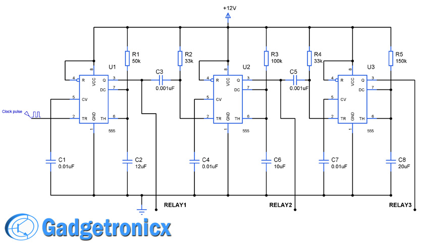
As i said before the three 555 IC’s was wired as monostable multivibrator that is each needs a negative going trigger to activate the devices connected through the relay.Initailly the negative trigger from the clock source activates the first timer IC making it to give high output activating the relay.The output pin of the IC1 was connected to the trigger input of the IC2.When the high output was given by the IC1 the output of the IC2 remains in low state but as soon as the output of the IC1 becomes low, it turns the output of the IC2 into high state thereby making it to activate the second relay in sequence.In the same manner the IC3 will be activated after obtaining low output from the output pin of the IC2.
The specifications of the R and C values play a significant role in the above circuit since it decides the time period of the output.The input clock pulse also plays a vital role in switching the circuits sequentially.In the above circuit the time period of input clock signal was about 5 seconds in order to make all the three IC’s switch correctly.You should give a low-high low clock as trigger input to the pin 2 of the IC1.In the above circuit IC1 will give logic 1 for 5secs and switch off since the trigger input will be low initially for 5 seconds.Then the IC2 will give high output for 1sec and IC3 will give high output for four seconds.For this reason the input trigger was selected in means of 5 seconds time period in order to make the circuit work perfectly making to switch the relays in sequence.The output time for the IC 555 was given by the formula
Do you what kind of circuit I can use that uses one push button to energize one relay and remain energized, then when I push the push button again, energizes a second relay and it also remains energized. I want to do this for 4 relays. Hope to hear from you soon.
Jansi,
Resistors and capacitors are essential to run the IC 555 as a multivibrator. The capacitor connecting one 555 IC to other is a coupling capacitor used to prevent false triggering. You need to have an understanding of how IC 555 works before going through this circuit here it is Working of IC 555 go through this to get clear idea about the working.
Harini,
See the whole circuit as an activator you will understand the working and get to know where to use this circuit. Consider a machine which does several process in steps like a conveyor belt with products moving over it. In each stage of conveyor movement a work has to be done in order to finish the product. The above circuit can be included in such places where the first stage of 555 will activate the conveyor and after some point of movement next IC will trigger the machine to perform any operation on the product such as packing, sealing and so. The next IC will do another operation, likewise you can add as many IC as you want based on the operation. After the complete cycle again the conveyor will gets activated which enable further movement. Hope it clears you up
Thangaselvam,
It will be useful where devices should be activated sequentially and remain activated for certain time period such as automation applications
Thank you for sharing this project.
I’m looking for a similar function but I need the outputs to be monostable so the relay outputs stay high until next trigger signal, like a sequential relay.
Could that be achived by simply omitting the RC-net?
I have looked at using D-flip-flop for this but the advantage of the 555 for me is direct drive of relays and 12V VCC.
David,
I convey my sincere apologies, there was a error in the circuit, IC 555 cannot drive a relay directly. You have to drive it through a transistor eventually along with the IC 555 (Corrected now) . With your description i believe Flip flop will be the best choice for your project.
Good work Sir…I would ask you some questions as follows:
1. after IC3 on so then in the second rounds which IC will goes on?! is it back to IC1 again or goes to IC2?
2. Can I use another extra IC in order allowing to control time’s speed up to 1 KHz/sec?
Amri,
1) After IC3 the cycle continues again starting from IC1. The clock pulse which feeds IC1 triggers the whole operation after IC1 get triggered it triggers IC2 and IC2 to IC3 this is how it works. You can also replace the Clock source with a simple push button interconnecting from Vcc to ground.
2) You can add additional IC and extend the device activated by the sequence, but i don’t get “control time’s speed upto 1Khz/sec” it would be more helpful if you brief this a bit.
Jeevitha,
relay here is used as an activator which could activate any devices such as motor, lights so and so. It depends on the purpose you use this sequential timer circuit for. Hope i answered your question

 Sequential timer circuit play a significant role in all sorts of timer applications such as switching devices in sequence for a given amount and switch appliances off after desired time.This circuit explains you the how to connect a simple IC555 as a sequential timer.IC 555 holds key in designing circuits for many applications and it also enables us to design a simple sequential timer to switch three relays in a sequence.The basic principle behind this circuit was connecting the Monostable multivibrator in sequence to make it work as sequential timer.
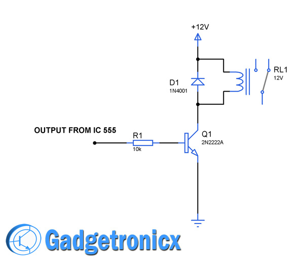 IC 555 is incapable of driving relay directly since the output current from a typical 555 IC is low. So we are going to use a simple transistor to switch the relay connected to it. Diode D1 was added to offer protection from the reverse current to the rest of the circuit.


Can you suggest what kind of transistor i can use for the 555 output to drive a 12 volts relay?
Hi Bobot,
That depends on the current consumption of your relay. Specify the current consumption and we might figure out the transistor that can be used for it
Do you what kind of circuit I can use that uses one push button to energize one relay and remain energized, then when I push the push button again, energizes a second relay and it also remains energized. I want to do this for 4 relays. Hope to hear from you soon.
AI,
I guess you can do that using Microcontroller easily rather than going for digital IC’s.
Which type of relay here used??? Mention relay name and specification?
Relay used here was 12V/100mA . You can substitute high current rated relays with this circuit by using high power transistors to drive it,
Why we using IC555 timer?why not other timer IC?
Jansi,
No specific reasons other than the chip is being versatile, low cost and widely available.
why we are using resistor and capacitor?
Jansi,
Resistors and capacitors are essential to run the IC 555 as a multivibrator. The capacitor connecting one 555 IC to other is a coupling capacitor used to prevent false triggering. You need to have an understanding of how IC 555 works before going through this circuit here it is Working of IC 555 go through this to get clear idea about the working.
nice circuit but am bewildered by the working of this circuit….can you pls guide
Harini,
See the whole circuit as an activator you will understand the working and get to know where to use this circuit. Consider a machine which does several process in steps like a conveyor belt with products moving over it. In each stage of conveyor movement a work has to be done in order to finish the product. The above circuit can be included in such places where the first stage of 555 will activate the conveyor and after some point of movement next IC will trigger the machine to perform any operation on the product such as packing, sealing and so. The next IC will do another operation, likewise you can add as many IC as you want based on the operation. After the complete cycle again the conveyor will gets activated which enable further movement. Hope it clears you up
can anyone plz tell any realtime application for this circuit
Thangaselvam,
It will be useful where devices should be activated sequentially and remain activated for certain time period such as automation applications
Thank you for sharing this project.
I’m looking for a similar function but I need the outputs to be monostable so the relay outputs stay high until next trigger signal, like a sequential relay.
Could that be achived by simply omitting the RC-net?
I have looked at using D-flip-flop for this but the advantage of the 555 for me is direct drive of relays and 12V VCC.
David,
I convey my sincere apologies, there was a error in the circuit, IC 555 cannot drive a relay directly. You have to drive it through a transistor eventually along with the IC 555 (Corrected now) . With your description i believe Flip flop will be the best choice for your project.
Many Thanks for your advice
David,
You are welcome.
Good work Sir…I would ask you some questions as follows:
1. after IC3 on so then in the second rounds which IC will goes on?! is it back to IC1 again or goes to IC2?
2. Can I use another extra IC in order allowing to control time’s speed up to 1 KHz/sec?
Amri,
1) After IC3 the cycle continues again starting from IC1. The clock pulse which feeds IC1 triggers the whole operation after IC1 get triggered it triggers IC2 and IC2 to IC3 this is how it works. You can also replace the Clock source with a simple push button interconnecting from Vcc to ground.
2) You can add additional IC and extend the device activated by the sequence, but i don’t get “control time’s speed upto 1Khz/sec” it would be more helpful if you brief this a bit.
why we are using relay in process control timer
Jeevitha,
relay here is used as an activator which could activate any devices such as motor, lights so and so. It depends on the purpose you use this sequential timer circuit for. Hope i answered your question