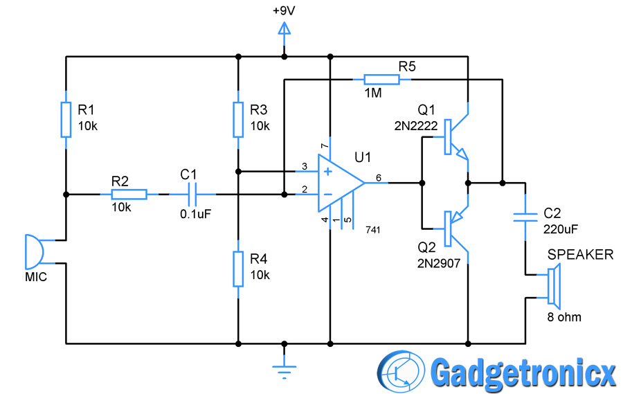
This article was meant you to understand the basic working of op amp 741 and how it was implemented in circuits.The IC 741 was the most common Operational Amplifiers used since it was very cheap and provides high gain value.There are three main modes that this IC 741 was used they are
PIN DESCRIPTION:
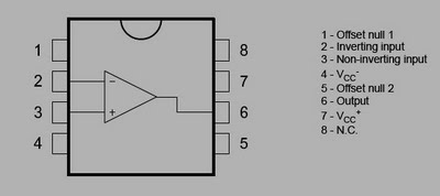
The IC 741 comprises of 8 pins as you can see in above pin diagram.
Pins 1&5-These two pins are meant for adjusting the offset voltage in order to obtain better gain.Offset voltages occur due to manufacturing process and there will be small differences which combine to look like a single input voltage error so this pins was used to adjust the voltage value and eliminate the error.
Pin 2-This was input pin which was used to invert the input voltage value and hence known as Inverting input.
Pin3-This was input pin which does not change the polarity of the given input voltage and hence known as non-inverting input.
Pin6-This output of the IC was obtained from this pin.
Pin 4&5-This was meant for positive and negative supply to the IC.
WORKING OF OP AMP 741:
1)INVERTING AMPLIFIER:In an inverting amplifier the input voltage enters through pin 2 and comes out of the pin 6 resulting in reversal of polarity.When the input voltage is positive output will be negative and if input negative out will be positive.
2)NON-INVERTING AMPLIFIER:In this type the input voltage enters the IC through pin 3 and leaves through pin 6.The polarity of the input voltage will obtain no change when coming out of the pin 6.
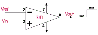
3)COMPARATOR:This mode was something different from the above two modes and this was used in a circuit that compares two input voltages one voltage is reference voltage (Vref) and the other is called the input voltage (Vin).Whenever the Vin rises or falls below the Vref value the polarity of the output changes thus making it to work as a comparator.
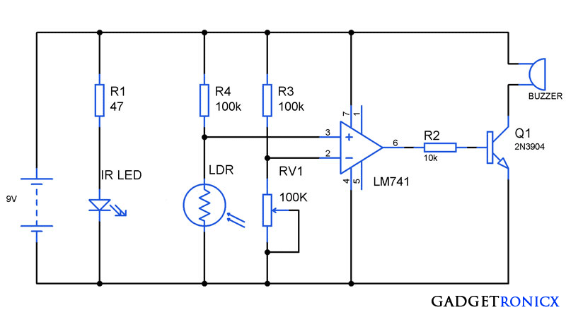
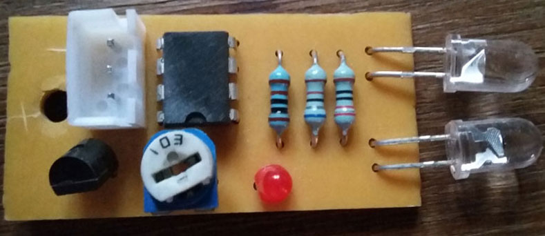
See a Intruder alarm circuit using IC 741 as a comparator.


start discussion