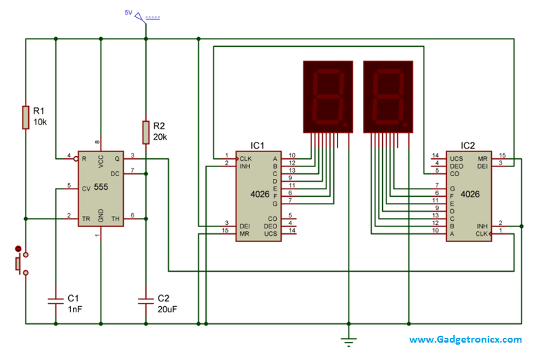
Two digit Counter Circuit can be seen in hospitals, banks etc for the purpose of counting any process. You might have seen the Single Digit Counter Circuit using 7 segment in our site and this is just an expanded version of the single digit counter. Here we are employing two 7 segments and two IC 4026 a seven segment Display Decade counter. And a IC 555 to feed the required pulse to the decade IC’s used in the above circuit. The whole circuit was designed to increment the count with a single push button switch. Lets move into the working of this counter circuit.
CIRCUIT DIAGRAM:
WORKING OF TWO DIGIT COUNTER CIRCUIT:
The working of the above circuit starts with the 555 where it was wired as a monostable Multivibrator. The important characterstics of a Monostable Multivibrator is as long as the pin 2 receives a positive trigger the output at pin 3 will be of low state. And when negative trigger was fed into the pin 2, the output at the pin 3 will go high for a specific period of time. This time was decided by the Resistor R2 and Capacitor C2 connected along with it. This timing is necessary to offer the debouncing delay to the circuit in order to avoid multiple input pulses at the same time to the trigger input. The equation governing the time period is given by T= 1.1 x R x C.
IC 4026 is a seven segment display decade counter which is used to drive a 7 segment display with input clock pulse. Here the clock pulse was obtained from the monostable multivibrator and fed into the pin 1 of the IC2 4026 since count value should be started from the 7 segment which is placed right hand side. Pin 2 was usually grounded since giving high signal to this pin will inhibit the input clock signal to pin 1. Pin 3 was meant for enabling the display and it was given high signal in both of the 4026 IC’s. The 4th pin was meant for enabling carry out and we left this pin unconnected and the same case applies to pin 14th of the 4026 IC.
Initially when the circuit is switched ON the 7 segments will indicate “00” count and as soon as the negative trigger was given to 555 high pulse will be obtained from pin 3. The high pulse was fed to IC2 and therefore it increments its count with each button press displaying 1,2,….9 in its seven segment. As soon as 10 counts was incremented by IC2 a high to low signal was obtained from its pin 5 which indicates the completion of ten increments.
The pin 5 of IC2 was connected to the CLK pin of the IC1. Therefore whenever 10 counts was completed by the 7 segment at the right side, the high to low signal at the pin 5 will feed a single clock pulse input to the IC1 and therefore the corresponding 7 segment will be incremented one value. In the same manner IC2 will count from 0 to 9 and then value in the IC1 will be incremented by one. Thus this counter circuit is capable of counting upto 99 and then returns to zero.
NOTE:
- Each push button switch differs in properties so as their debounce delay, so if you face problem in multiple increments of 7 segment values increase the values of Resistor R2 and Capacitor C2.
- If you want your circuit to automatically count the values, then replace the Monostable Multivibrator with Astable Multivibrator with assigned time period.

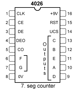
Hi in the circuit diagram above there is no pin 16 mentioned for the 4026 I was wondering if they need to be connected to the positive terminal?
Yes 16th pin is Vcc you need to connect it to the power supply. For the sake of simplicity of schematic it has been omitted.
Am I suppose to create a type of voltage divider in order for pin 2 to drop 1/3 of its voltage, because I’m following the circuit diagram right I think but cant seem to get it to even change from 00.
Also for your 7th and 8th pins on the display, do you connect both of them to ground?
im working on this two digit counter with 555 ic, 4026 ic and we have this 100k potentiometer, it’s not counting right, the pulse is not working but whenever i click the reset button continuously the 1st 7 segment counts but the 2nd one isn’t counting. seems like the 1st one does the job of the 2nd 7 segment. that’s my problem. help pleaseee. i don’t know what’s wrong with my circuit but i followed the schematic diagram carefully.
Camille,
Kindly note that this is a manual counter circuit and the button given in this circuit is not Reset, its the counter button. Whenever you want to increment the count you press the button its completely manual. If you want your counter to increment automatically, use IR to trigger the count -> https://www.gadgetronicx.com/people-object-counter-circuit-diagram-ic555/
Sir can you made video of this circuit
Well I can give a try
Kindly, am looking for a very simple BCD4026 manual electronic counter circuit that has a buzzer which will be ON when number of manual counts/clicks reaches 10, and the buzzer will stay ON until I hit a reset button. Please, any ideas or schematics around that can d that?
Ahmed,
Consider this connect the 15th pin MR to pin 2 INH and to a pull down resistor of 10K . Connect a buzzer to CO pin and also to the 15th pin MR with a push button between them.
hello sir, am doing a project on transistor based application.instead of ic555 am using LDR and transistor.can i use any other counter ic instead of 4026.plz help me sir.
Hi Asha,
Of course you can, try searching for Counter ICs in the internet and you can make your pick. But be aware the way they work will differ, so check the corresponding datasheet
Hi Frank,
I want to turn off/on the display. I discovered that grounding pin 3 and pressing the reset button before powering up the circuit disables the display. I can then jumper pin 3 to vcc to enable the display, but then hoe do I turn it back off, and then on, then off, etc?
I’m lost as how to do this in order to save battery power as I leave it on overnight. thanks.
Hi Phil,
Am not sure I got your question completely. Do you want to turn the whole system off? If that is the case add switch from the + line of the battery that will be the simplest way to do. If you want to ON/OFF only the display as per you wish then you can SPDT switch where you can connect Pin 3 of 4026 IC and toggle them between ground and VCC.
Hi Frank,
I want to leave the full circuit on, to count the number of times the display is incremented by my PIR ( which I have sorted ) but save battery power and flick a switch/press a button to see the display at intervals, I don’t want to loose the count.
Sorted. Thanks Frank, SPDT one side to Pos other to Neg, works a treat.
Took my time though didn’t I?
Regards Phil Dee
Can you provide me the truth table and k-diagrams because i need this for a school project
Thank you
Respect (:
How do you automate the PTM button in the bottom left?
Can I use a 12 volt power supply with this circuit if I use a resistor for each segment of the displays and if so what size resistors should I use ?
Hi Rob,
Yes you can. Using a 12v supply will force 4026 to give 11.95v (approx) in the output pins. So you should be using resistor of value R = [ 11.95 – 2 ( voltage drop for a typical LED) ] / 20ma (current consumption of a LED)
Supply voltage is 5 how about current,? I want to test the circuit in a power supply
Sir is this compatible with a common Anode 7 segment display?
Onjie,
No common cathode should be used for this circuit.