Here am yet again with a simple push pull amplifier circuit using Vacuum tubes. This design is very simple and brings good audio quality if properly built. There is a lot on every block of the circuit on the internet, so I`m gonna be going into little detail about this. Before looking the actual design of this amplifier let us have a quick look at its specs.
Input Sensitivity – 200mV (the line level of my phone Xperia Z3 Compact)
Output Power – Should be around 15W, but I`ve been using a salvaged transformer with a much lower rating, and it saturates or something at around 7-8W.
Efficiency – Haven`t measured it, but it should be around 50%
THD+N – I don`t have the means to measure it, but according to the datasheet of the el84, and considering the previous stages, it should be around 5% at 15W, but almost all distortion is second order, so you`ll find the sound very sweet and smooth.
PUSH PULL AMPLIFIER CIRCUIT:
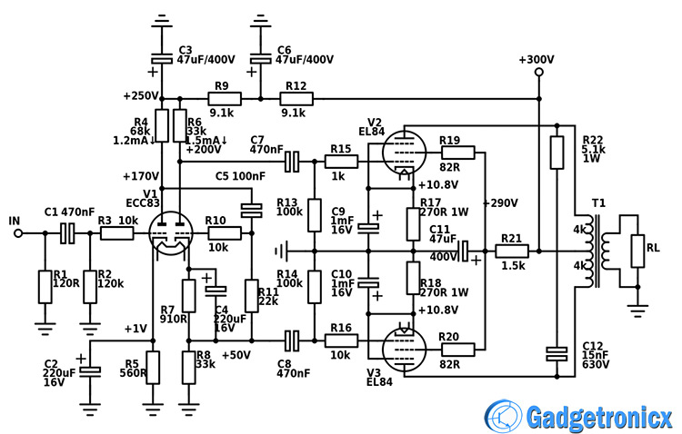
The first two stages use the most famous twin triode tube the ECC83/12AX7/6N2P. It has the highest gain of all triodes, which makes it suitable for the task. Alternatively I also designed a circuit with a pentode voltage amplifier stage, because currently the ECC83 is right on the edge of its gain capabilities and you can`t push it further without compromising distortion. But I chose to upload this design, because it uses very common tubes and has quite a sweet distortion tone.
FIRST STAGE:
The first stage is a very typical preamp voltage amplifier stage in a common cathode configuration. It possess a gain of around 55, bringing even the lowest line levels to sufficient voltage to drive the power amp.
SECOND STAGE:
The second stage is known as a cathodyne, and works as a phase inverter/driver. Since tubes don`t come in complementary pairs as transistors, you have to drive the power tubes in 180 dgs out of phase to get the push pull circuit. When one tube swings up, the other swings down with the same amount, and vice versa. The phase invertor uses the most common circuit (the Cathodyne), which when properly built can have a very good balance and can often be used in a Hi-Fi application.
POWER STAGE:
The power stage is a class B push pull amplifier and as already stated, when one tube increases conduction the other decreases it by the same amount. Such a topology has very big advantage over single ended designs. In the output transformer, theoretically currents are equal and opposing, which cancels any DC magnetization. And making the output transformer smaller and without air gap improves low frequency response. Also as currents are equal and opposing any even order distortion will be cancelled and all odd order distortion summed. When running the amp with a dummy load, you can actually hear the transformer vibrating in the odd order distortion. This gives you a good idea about the distortion rating of the amplifier. I consider it good, with this design.
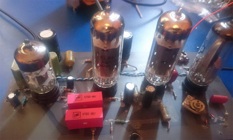
The output stage is a very typical topology you can find all over the internet. It’s just a couple of EL84`s working in push pull configuration in a pentode mode. I`ve made it with a fourth tube which I haven’t included in the circuit. It`s a magic eye indicator tube to give a rough estimate on the output level.
Hope you all like this design. Do build it and post your outcome in the comment box below, happy DIY 🙂 fellas.
I just wanna make my vaccum tube glow a little,not for any useful application, just becouse it looks cool. How do i wire it? It’s a Philco 1063, i guess it’s the same as all the 7 pin tubes, but i coudn’t find any schematic. Plz help


I just wanna make my vaccum tube glow a little,not for any useful application, just becouse it looks cool. How do i wire it? It’s a Philco 1063, i guess it’s the same as all the 7 pin tubes, but i coudn’t find any schematic. Plz help