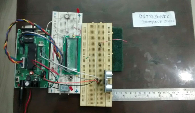
Ultrasonic waves are of great use and holds key in fields such as automation, marine and so. One of the familiar and trusted application of Ultrasonic waves are range and distance detection, you might have seen some of these in robots to detect obstacles and in automated factories. Similarly we are going to build Ultrasonic distance meter to measure the distance between the module and an object, this will be extremely useful for robotic applications.
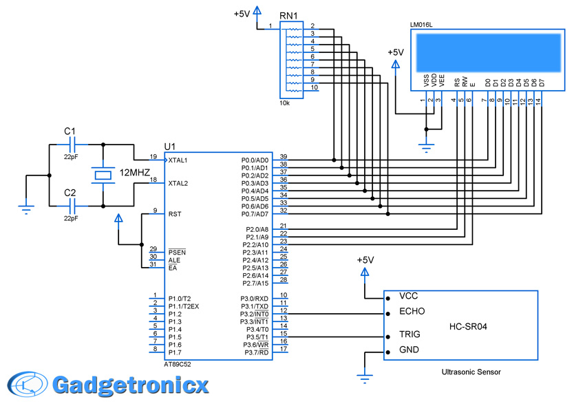
SCHEMATIC DESIGN OF ULTRASONIC DISTANCE METER:
PARTS REQUIRED:
Here is a list of parts required to build this project. We have added direct links to buy these parts in the below table. Since we are an affiliate marketing partner of “Amazon.in” we will get a referral fee for every purchase you make, which would make you a contributor for our development.
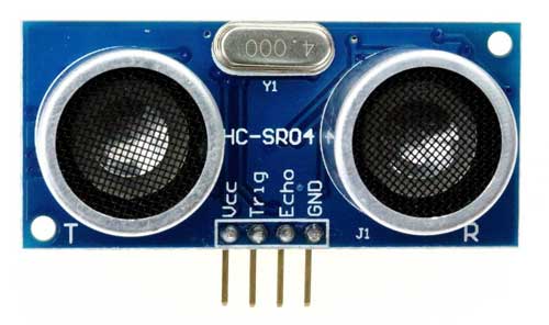
HC-SR04 is an ultrasonic ranging module designed for embedded projects like this. It has a resolution of 0.3cm and the ranging distance is from 2cm to 400cm. This module transmits an ultrasonic signal, picks up its echo, measures the time elapsed between the two events and outputs a waveform whose high time is modulated by the measured time which is proportional to the distance.
1) VCC : 5V DC supply voltage is connected to this pin.
2) Trigger : The trigger signal is to start the transmission of waves which must be a pulse with 10uS high time. When the module receives a valid trigger signal it issues 8 pulses of 40KHz ultrasonic sound from the transmitter. The echo of this sound is picked by the receiver.
3)Echo : At this pin, the module outputs a waveform with high time proportional to the distance.
4) GND: Ground is connected to this pin.
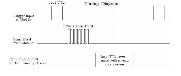
This timing diagram explains the way this module measures the distance. A pulse trigger input to the module will enable it to produce a burst of 8 sonic pulse of 40Khz. When the pulse hits the obstacle it reflects the ultrasonic waves as echo which is sensed by the echo pin of the module. The echo signal can be obtained from the Echo pin of the Ultrasonic module. The length of the of echo pulse is proportional to the distance of the object/obstacle. Refer the “Data Sheet” for more information about this module.
USING 8051 TO MEASURE ECHO PULSE:
Now we are clear about the module pins and its operation let’s see how to make this work with 8051 to measure distance. The measurement of Echo pulse can be done with the help of external Interrupt and Timer modules of AT89S52 Microcontroller. In capture mode when external pulse is fed to the interrupt the timer starts counting and will stop only after the state of pulse is changed. Steps to follow to program controller as a capture device.
Initialize Timer0 module as 16 bit timer with Gate bit as 1.
Making Gate bit as 1 will transfer the control of timer to external interrupt pin INT0.
When there is an interrupt pulse timer 0 starts counting and stops as soon as the interrupt disappears.
The value in the Timer 0 (TH0 and TL0) gives the time period or length of the pulse.
OPERATION:
Connect the Trigger pin of the HC-SR04 module to any I/O pins of 8051 controller.
Connect the Echo pin of the module to interrupt pin INT0 of the Microcontroller.
Send a pulse of minimal timer period 10us, this will make the Ultrasonic module to send burst of data.
The reflected waves will be sensed by the module and it exhibits the output in Echo pin logic high or 1 to INT0 pin of Microcontroller.
This creates an interrupt and Timer 0 will start counting.
When the pulse from echo pin alters its state to logic 0 or low the timer 0 stops counting
The length of pulse from echo pin is proportional to the distance at which the object is located.
The value in the Timer 0 gives the distance of course with some simple calculations.
CALCULATION:
According to the data sheet the distance can be given by the formula :
Distance in cm = Timer 0/58
Distance in inch = Timer 0/148
CODE:
#include<REGX52.h>
#define port P2
#define dataport P0
int cms;
sbit trig=P3^5;
sbit rs=port^0;
sbit rw=port^1;
sbit e=port^2;

void delay(unsigned int msec)
{
  int i,j;
  for(i=0;i<msec;i++)
  for(j=0;j<1275;j++);
}

void lcd_cmd(unsigned char item) // Function to send command to LCD
{
  dataport = item;
  rs= 0;
  rw=0;
  e=1;
  delay(1);
  e=0;
  return;
}

void lcd_data(unsigned char item) // Function to send data to LCD
{
  dataport = item;
  rs= 1;
  rw=0;
  e=1;
  delay(1);
  e=0;
  return;
}

void lcd_data_string(unsigned char *str) // Function to send string to LCD
{
  int i=0;
  while(str[i]!='\0')
   {
    lcd_data(str[i]);
    i++;
    delay(1);
   }
return;
}

void send_pulse(void)
{
  TH0=0x00;TL0=0x00;
  trig=1;                  //Sending trigger pulse
  delay(5);                //Wait for about 10us
  trig=0;                  //Turn off trigger
}

unsigned int get_range(void)
{
  long int timer_val;
  send_pulse();
  while(!INT0);          //Waiting until echo pulse is detected
  while(INT0);           //Waiting until echo pulse changes its state
  timer_val=(TH0<<8)+TL0;
  lcd_cmd(0x81);
  lcd_data_string("output:");
  lcd_cmd(0x8a);
  if(timer_val<38000)
   {
    cms=timer_val/59;
    if (cms!=0)
     {
      lcd_data(cms+48);
     }
   }
  else
  {
   lcd_cmd(0x06);
   lcd_data_string("Object out of range");
  }
  return cms;
}

void main()
{
  lcd_cmd(0x38);
  lcd_cmd(0x0c);
  delay(2);
  lcd_cmd(0x01);
  delay(2);
  lcd_cmd(0x81);
  delay(2);
  lcd_data_string("start");
  delay(20);
  TMOD=0x09;//timer0 in 16 bit mode with gate enable
  TR0=1;//timer run enabled
  TH0=0x00;
  TL0=0x00;
  P3|=0x04;//setting pin P3.2
  while(1)
  {
   get_range();
   delay(2);
  }
}
WORKING VIDEO:
NOTE:
You can use this method to any robotic path guidance application.
You can get more range by replacing the sensor module we used above.
plz help me if any one run this program because when i gave the power it automatically stuck at M letter without show another thing if anyone have the write code plz reply


Lcd display just start and how to measure distance plz give me solution of that problem
How to display distance by ultrasonic sensor and they just display start in lcd ? Give me solution of that problem.
plz help me if any one run this program because when i gave the power it automatically stuck at M letter without show another thing if anyone have the write code plz reply
is this possible to interface two ultrasonic sensors with p89v51rd2 microcontroller???
Yes it is possible to connect two Ultrasonic sensors to it.