 |
| Serial Communication using 8051 |
Microcontrollers need to communicate with external devices such as sensors, computers and so on to collect data for processing. Data communication is generally done by means of two methods – Parallel and Serial mode. In parallel mode data bits are transferred faster using more data pins. But when comes to a Microcontroller, we cannot afford to dedicate many pins for data transfer. UART or Serial communication in 8051 microcontroller will allow the controller to send and receive data’s just by using two pins
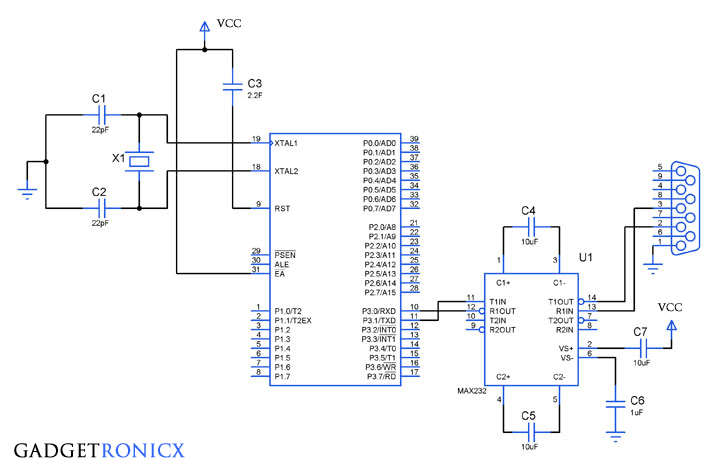
Serial Communication uses only two data pins to establish communication between Microcontroller and external devices. In this mode of communication data is transferred one bit at a time. This article describes Interfacing of 8051 with PC to establish communication through its serial port RS232.
RS232 AND MAX232:
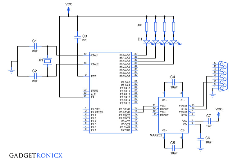
To establish communication between a controller and PC, we must use serial I/O protocol RS-232 which was widely used in PC and several devices. PC works on RS-232 standards which operates at a logic level of -25V to +25V. But Microcontrollers use TTL logic which works on 0-5V is not compatible with the RS-232 voltage levels.
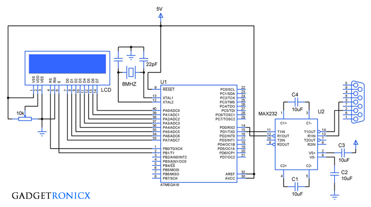
MAX232 is a specialized IC which offers intermediate link between the Microcontroller and PC. The transmitter of this IC will convert the TTL input level to RS-232 Voltage standards. Meanwhile the receiver of this IC will convert RS-232 input to 5V TTL logic levels. Read the complete working of MAX232 IC.
SCON REGISTER:
 |
| SCON Register |
It a bit addressable register used to set the mode in which serial communication takes place in the controller. The above figure shows the configuration of the SCON register. Here is the list of functions of each bit.
 |
| Serial Mode of 8051 |
SM0, SM1: Serial Mode control Bits
SM2: Multiprocessor mode control bit, logic 1 enables Multi processor mode and 0 for normal mode.
REN: Enables Serial reception. If set, it enables the reception otherwise the reception is disabled.
TB8: It is the 9th bit of the data that is to be transmitted.
RB8: It is used in modes 2 and 3, it is the 9th bit received by the microcontroller.
TI: It is known as Transmit Interrupt flag which is set by hardware to indicate the end of a transmission. It has to be cleared by the software.
RI: It is known as Receive Interrupt flag which is set by hardware to indicate the end of a reception. It has to be cleared by the software.
BAUD RATE:
It is defined as number of bits transmitted or received per second and usually expressed in Bits per second bps. For mode 0 and mode 2 the baud rate is determined by means of 1/12, 1/32 or 1/64 of crystal frequency whereas for mode 1 and 3 it is determined by means of timer 1.
 |
| Baud Rate by Timer1 |
Learn how to configure Timers in 8051.
SBUF REGISTER:
It is a 8 bit register that holds the data needed to be transmitted or the data that is received recently. The serial port of 8051 is full duplex so the microcontroller can transmit and receive data using the register simultaneously.
CODE:
#include<reg51.h>
void initialize()     // Initialize Timer 1 for serial communication
    {
     TMOD=0x20;    //Timer1, mode 2, baud rate 9600 bps
     TH1=0XFD;      //Baud rate 9600 bps
     SCON=0x50;
     TR1=1;             //Start timer 1
    }
void receive()        //Function to receive serial data
   {
    unsigned char value;
    while(RI==0);       //wait till RI flag is set
    value=SBUF;
    P1=value;
    RI=0;                    //Clear the RI flag
   }
void transmit()       // Funtion to transmit serial data
   {
    SBUF='o';            //Load  'o' in SBUF to transmit
    while(TI==0);      //Wait till TI flag is set or data transmission ends
    TI=0;                  //Clear TI flag
    SBUF='k';
    while(TI==0);
    TI=0;
   }
void main()
{
 while(1)
  {
   initialize();
   receive();
   transmit();
  }
}
Initialize() – Initialize timer for baud rate and set mode for serial transmission. The above program will receive a character from PC and in return transmits “ok” back to PC. This code have three parts initialize() ,receive() and transmit() to perform the process of serial communication. This can be tested using Hyperterminal software after connecting your controller to PC through RS232.
- Initialize() – Enables the Serial communication by configuring TMOD and SCON registers.
- Receive() – Check whether the microcontroller has received data from PC.
- Transmit() – Transmit bits ‘o’ and ‘k’ to form the message “ok” back to PC.
Hope this tutorial taught you about using Serial communication in 8051 Microcontrollers. Do check out other 8051 tutorials in our website. Post your feedback/ queries in the comment section below. I will be happy to answer them.

typo when calling the function, it should be initialize() but its initalize(). Anyway thanks for the code.
Shreyas, Thanks for pointing it out. Corrected now.
Your welcome 🙂
How can I use 8051 in shIFT register serial communication mode
thank you for the code
Bonham,
You are welcome.