
Spy Bug circuits are something that’s used when we need to listen to conversation without being noticed or to simply put to spy on a person. Generally Spy bug circuits are constructed using a Mic, amplifier and speaker. The medium can be wired or wireless depending on the application for which we are going to use. This article explains the construction of a simply wired spy bug circuit built around opamp IC741.
WORKING OF WIRED SPY BUG CIRCUIT:
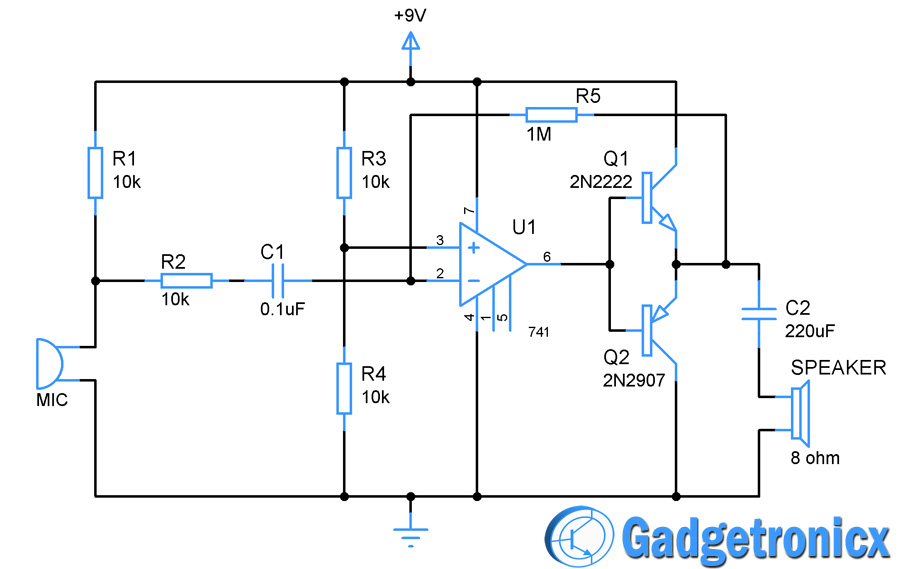
This circuit can be divided into three sections for better understanding. First part comes the receiver, it was built using the electrect Microphone (Mic) and Resistor R1. The microphone converts the sound into electrical pulses or signal. R1 is used to adjust the sensitivity of the Mic and can be altered if you wish to alter the Mic sensitivity. R2 serves as a volume control and C1 was used to remove the DC component from the signal.
Next comes the preamplifier stage which was built using Opamp IC 741. This IC was wired as an inverting amplifier here hence the input signal was passed through the inverting terminal of the IC741. The positive terminal of the non inverting terminal was biased using the voltage divider R3 and R4. R5 resistor was used to provide negative feedback for the opamp which in turn control the gain of the opamp.
The next stage comes the amplifier built using two transistor 2N2222 and 2N2907. Both these transistors are connected in Push Pull configuration which means one of the transistor amplify positive half of input signal while other deals with negative half. Thus we obtain amplified 180 degree out of phase signal from this Push pull amplifier. This signal is then passed through Cap C2 to filter out any DC components and then to the speaker or any sounding element.
NOTE:
- You can substitute speaker with a 60 ohm headphone as a listening device.
- Since it is a wired bug you will get much clarity of the signal but comes in cost of wiring from source to destination.
- Sensitivity of the mic can be adjusted by altering the value of R1.


Hi my friends and especially the people of the Chinese people. I have a question. Is it possible to have a Transistor Npn Master for all types of transistors even if it works 60% and the Transistor Pnp Master even if it works 60%
Hi Farooq,
“Master of all transistors” sorry it’s bit hilarious and am not sure what do you mean by this. Do you mean to ask what’s most commonly used NPN and PNP transistor ?
Does volume increase with the increase in r2
With decrease in R2 you can increase the volume. Replace R2 with a 10K pot and you will can set your desired volume.
We can add a little modification, a clocking cct and a USB driver and female port to which we can digitize the sound output and store it in removable media. Of course with the write and read buttons included.
Frank,
That sounds like great upgrade 🙂
Sir …I need applications and documentation of listening bug..
Everything listed above
It will have too much distortion .(Transistors are not polarized.)
I need wireless remote control circuit for 6volt dc motor operate.please help me
Ram,
This link might help you https://www.gadgetronicx.com/radio-frequency-rf-remote-control-circuit/