Devices such as transformers are usually used where a certain voltage level is required but unfortunately transformers are not feasible everywhere because of its robust size and price. To deal with instants we use special yet simple circuit called voltage doublers which is capable of doubling the input voltage fed to it Ex. If we fed Vin as 6 v we will get 12 v as Vout.
WORKING OF VOLTAGE DOUBLER CIRCUIT DIAGRAM:
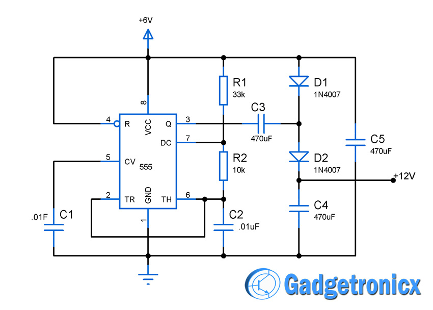
The main principle behind the working of this circuit is the capability of charging and discharging of a capacitor. In this Circuit timer IC 555 serves as an oscillator for the entire circuit. The IC 555 was wired as an astable multivibrator which generates square signal of frequency 2KHz. The frequency of the astable multivibrator depends on the components R1,R2 and C2.
So the Pin3 of the IC 555 emits square wave of 2Khz. When logic level of the output signal is high or 1 the diode D2 and capacitor C3 is in forward biased condition. This makes the capacitor C3 to get charged and the diode D1 is used to protect the C3 from getting discharged when the logic goes low. This action in turn makes the capacitor C4 to gets charged with a combined voltage from C3 and power supply.
This makes the output voltage to be doubled from that of the input voltage source. This operation was done by these components C3,C4 and D1,D2. Therefore at the point of output (between D2 and C4 ) we will obtain an output voltage of about 12V.
NOTE:
Make sure your input voltage stays between 3v to 12v or it may destroy the timer IC 555.
What is the difference between AC capacitance and DC capacitance and why in all inductive loads DC capacitors are used infrant of 230V AC 50hz and if required then how to calculate the capacitors values?

 Devices such as transformers are usually used where a certain voltage level is required but unfortunately transformers are not feasible everywhere because of its robust size and price. To deal with instants we use special yet simple circuit called voltage doublers which is capable of doubling the input voltage fed to it Ex. If we fed Vin as 6 v we will get 12 v as Vout.


Can I give a 12v input to get 24v output?
Can you send me the Simulation result of this circuit. Because when I did the Simulation in kiva i got the wrong output.
Shekhar,
Software simulations are not always reliable, kindly put together in a breadboard and look for the result.
What is the difference between AC capacitance and DC capacitance and why in all inductive loads DC capacitors are used infrant of 230V AC 50hz and if required then how to calculate the capacitors values?
Hi Yogesh,
Too big topic to cover in a comment. Refer this link
http://www.electronics-tutorials.ws/accircuits/ac-capacitance.html