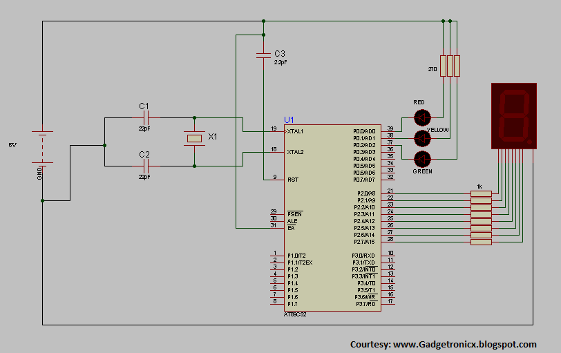
Microcontroller based Traffic light systems was one of the basic project that one can do with a microcontroller to understand its concepts and working.In this post i would like to share the hardware and program code of a Traffic light system using 8051 microcontroller with you all.Here in the above circuit you can see that we are using a seven segment to display as a counter and three LED’s to perform the traffic lights operation.The crystal we are using is of 4MHz crystal and the Microcontroller was AT89C52.
The LED’s was connected in a common anode mode so that the Microcontroller was used as a sink here.The Red color was made to flash for 10 seconds and yellow, green were assigned glow for five seconds each.The resistor values for LED’s should be of 470 ohm and to the 7 segment should be around 1K.
COMMON CATHODE 7 SEGMENT:
The above circuit uses a Common cathode 7 segment which have some unique characterstics.As you can see in the above 7 segment pin configuration that there is two common GND and LED’s are connected in a Common cathode manner.That is when ever the pin was made high the corresponding LED will glow.If the pin was low the corresponding LED will go into off state.This was the working of the 7 segment.In the traffic light systems circuit the a,b,c,d …h pins of the 7 segment was arranged in order so i have connected it in a continuous manner.While you are connecting the 7 segment to the Microcontroller you have to connect the port pin P2.0 to the pin a of the 7 segment then P2.1 to b, P2.3 to c it goes on and ends up to pin h.This is the way that the hardware should be constructed and now lets move into the programming part of the Microcontroller.
PROGRAM:
The program code was developed in Embedded C language and was done in Archimedes IDE 8051 software.The code of the above system was given below.
#include<stdio.h>
#include<reg51.h>
void delay(void);
void dat(void);
void dat1(void);
unsigned char a[10]={0x6f,0x7f,0x07,0x7d,0x6d,0x66,0x4f,0x5b,0x06,0x3f};  //Assigning arrays for lighting up the 7 segment in reverse order from 9 to 0
unsigned int i,j,s,k;            //Assigning integers
void main()
  {
    P0=0xfe;                      //Giving 1111 1110 to port 0 making red light to flash.
      {
        dat();                       //calling dat function
        P2=0x00;               //Switching 7 segment off after one operation
       }
     P0=0xfd;                  //Giving 1111 1101 to port 0 to make yellow light to flash
      {
        dat1();                   //calling out dat1 function to display numbers from 4 to 0
        P2=0x00;
      }
     P0=0xfb;                 //Giving 1111 1011 to port 0 to make green light ON.
      {
       dat1();
       P2=0x00;
      }
   }
  void dat(void)
    {
     for(i=0;i<=10;)            //Calling out the array from 0 to 10
       {
        P2=a[i];                    //Giving the array elements to Port 2
        i++;                          //Incrementing array elements
        delay();                    //Calling out delay function
       }
    }
  void dat1(void)
    {
      for(i=5;i<=10;)           //Calling out the array elements from 5 to 10.
        {
         P2=a[i];
         i++;
         delay();
        }
    }
  void delay(void)             //function for creating delay by means of increment
    {
      for(s=0;s<=200;s++)
       {
         for(k=0;k<238;k++);
       }
    }
WORKING VIDEO:
EXPLANATION:
The #include files of the program includes the registry files of the 8051 Microcontroller.The program was classified into four sections which is
“void dat”- Array for the numbers to display while the red light is ON.
“void dat1”-Array for the numbers to display while the yellow and Green light is ON.
“void delay”-Program to generate delay between the numbers displayed in 7 segment.
Initially the unsigned char array was given in the form of hex values.Totally there was ten number of elements in a array to display the numbers from 0 to 9.The Microcontroller was used as a source of sinking current for the LED’s since the P0 will put up a high impedence state if logic 1 was written to it.Delay was given with each increments of the elements in the array by calling out the delay function.Hope i have explained this clearly.
Hi Abhinav,
Refer to the 7 segment pin diagram and connect from P2.0 to ‘a’ pin of 7 segment display. Connect the rest of port pins to 7 segment in order b,c,d…f as such.
hello Mr. Donald. nice meeting u here.plz I need ur help urgently.it is concerning my final year project on two way traffic light controller using microcontroller.i cant find the circuit diagram and other relevant information concerning the project..plz help me out.Regards Sajor Barrie


using Traffic light system 8051 Microcontroller circuit and program how to get 1ms,5ms,10ms,15ms,20ms,25ms,30ms,35ms time delay output and disply.
require output display 1ms,5ms,10ms.
sir could you show me how the two seven segment displays are connected to the circuit
Hi Abhinav,
Refer to the 7 segment pin diagram and connect from P2.0 to ‘a’ pin of 7 segment display. Connect the rest of port pins to 7 segment in order b,c,d…f as such.
In description u mentioned 470ohm register value for LED nd in diagram u print 270ohm.. which register value we will take for complete output..?
Anything should work
will the crystal frequency remain 4MHz for 8051 too? or is it different?
hello Mr. Donald. nice meeting u here.plz I need ur help urgently.it is concerning my final year project on two way traffic light controller using microcontroller.i cant find the circuit diagram and other relevant information concerning the project..plz help me out.Regards Sajor Barrie
I want to see working video kindly tell me how i can get its video?
I have used IDE 8051 to code this program so dont get confused.
Pleez Can u tell me The version of Mico C that u used with At89s52 cause i can’t find that type any where !!!
Thank u