Pump controller circuits hold great importance to manage the water efficiently. Automating water fill pumps and sump pumps based on the availability of the water in the tank or sump are the best way for effective management. Here we are going to do a similar thing by automating a sump pump and expelling the water automatically once the sump is filled. This circuit is useful to implement in Underground Rain water harvesting tanks or sewer systems. Also, this pump controller circuit can be tailored to work as a normal water level controller for a water tank or a cistern.
WORKING OPERATION OF SUMP PUMP CONTROLLER:
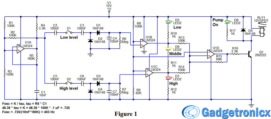
Please refer to Figure 1 (schematic diagram) for this discussion. The heart of the oscillator is U1A, R1-R5, and C1. R1and R3 divide the V1 supply voltage in half and their combined resistance is R1*R3/(R1+R3) = 50K. Since R2 = 100K, when the output of U1A switches from ground to 15 volts (+V1), the junction of U1A+, and R1, R2, R3, switches from 4 volts to 8 volts. R5 starts charging C1. When C1 charges above 8 volts, the input of U1A- is higher than U1A+. That causes the output of U1A to switch to 0 volts. In turn, the junction of U1A+, and R1, R2, R3, switches from 8 volts to 4 volts. R5 begins to discharge C1. When C1 discharges below 4 volts, the input of U1A- is lower than U1A+. The output of U1A switches from 0 volts to 12 volts (+V1), the junction of U1A+, and R1, R2, R3, switches from 4 volts to 8 volts. R5 begins to charge C1 and the cycle keeps repeating. C1 is constantly ramping up and down between +V1*1/3 (4V) and +V1*2/3 (8V). The really cool thing is that this circuit oscillates at the same frequency even if the supply voltage +V1 changes!
The output of U1A is a 12 volt square wave with a frequency of about 400 Hertz. The output is connected to C2 and C5 which feed one side of an electrode pair to detect the water at a low-level and a high level. The electrodes can be adjusted to provide any lower and higher levels the user desires. S1 and S2 merely represent the two electrode pairs. C2 and C3 are connected to the lower level, electrode pair, while C5 and C6 are connected to the higher level electrode pair. C3 is connected to D1, D2, C4, R6 which form a charge pump that is connected to the input of U1B+. If the water is lower than the low-level electrode, no oscillating current passes to C3 and the charge pump is OFF. R6 discharges C4 so the output voltage to U1B+ is zero and below the 5.4 volt reference at U1B-, provided by R8 and R9.
Therefore the output of U1B is zero which lights LED, D5 (green), to indicate a low-level in the tank. When the tank level rises above the low-level electrode, the oscillating current passes through the water to C3. C3 passes the AC current through D1 and D2 to pump charge onto C4. When C4 charges above 5.4 volts, the U1B output switches from low to high. This turns OFF LED D5 (low-level) and turns ON LED D6 (yellow, mid level) because the high level charge pump is OFF and the U1C output is low. Though the output of U1B is high, the positive feedback through R15 and the low output from U1C coupled through R14, set the input of U1D+ to about 3 volts. Since the input at U1D+ is less than the 5.4 reference voltage, the output of U1D is low and the sump pump would remain OFF.
If you examine the charge pump formed by C6, D3, D4, C7, R7, that is connected to the U1C+ input, you will see that it operates exactly like the low-level circuit. So when the water connects the high level, C5, C6, electrode pair, C7 charges above the 5.4 reference voltage and the output of U1C goes high. This causes two things to occur. First, LED D6 (mid level) turns OFF and LED D7 (red, high level) turns ON. Second, since U1B and U1C are both high, R13 and R14 pull the input of U1D+ to 6.2 volts which is above the 5.4 reference voltage. The output of U1D switches high. This turns ON Q1 through resistor R16 and energizes relay RLY1.
This turns on the sump pump and lights the pump ON LED D8 (green). When the pump is ON the water level in the tank goes down. When the high level, C5, C6, electrode pair is dry, the D3, D4 charge pump is OFF (goes to zero), U1C+ goes below the reference voltage, U1C output goes low, LED D7 (red, high level) turns OFF. Since U1B output is still high, LED D6 (yellow, mid level) turns ON. Since U1D is high and U1B is high, the voltage input to U1D+, about 7.5 volts, maintains the pump ON status. When the water goes below the low-level electrode, The low-level charge pump goes to zero and so does the output of U1B. When this occurs, the R13 and R14 are zero and the resulting input voltage to U1D is about 4.4 volts, this causes the output of U1D to switch low, thus turning OFF the sump pump.
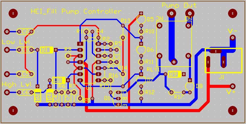
CHANGING THE SUMP PUMP TO FILL PUMP CONTROLLER CIRCUIT:
Let’s say that you wish to use this circuit to fill a tank when it gets low. Simply reverse the inputs to U1B and U1C. That is to say, connect the charge pumps to the U1B-, and U1C- inputs, and connect the U1B+ and U1C+ inputs to the R8, R9 reference voltage. Realize the that LED D7 will represent a low tank and LED D5 will now represent a full tank. Now when the tank is full, U1B and U1C will be low and turn OFF the fill pump. When the tank is below the low-level, U1B and U1C will be high and switch the pump ON to fill the tank.
The best part about this circuit is that uses AC current on the electrodes which will keep them from corroding or forming scale which would degrade them and cause them to quit working. This means greater reliability and long life.
It is complicated… much could be solved with LM555 chip with some conditioning… Pin 2 (Trigger) pulled to 0V via “HIGH LEVEL” switch (to ground) starts and latches pump on… and 0V to pin 4 (Reset) “LOW LEVEL”
switch to ground, stops pump. Of course, the output of LM555 will need to drive the 2n2222 Q1 as yours does. If ever BOTH SWITCHES ARE CLOSED, like if the low level is stuck, the pump runs until the high level switch opens. This is proper.
And that would be for the sump pump controller to pump out, not your fill circuit.


 Microcontroller")

It is complicated… much could be solved with LM555 chip with some conditioning… Pin 2 (Trigger) pulled to 0V via “HIGH LEVEL” switch (to ground) starts and latches pump on… and 0V to pin 4 (Reset) “LOW LEVEL”
switch to ground, stops pump. Of course, the output of LM555 will need to drive the 2n2222 Q1 as yours does. If ever BOTH SWITCHES ARE CLOSED, like if the low level is stuck, the pump runs until the high level switch opens. This is proper.
And that would be for the sump pump controller to pump out, not your fill circuit.
The circuit is amazing, works perfectly I hope. Your work surely takes a fancy to everyone.
Best of luck…!!!
Thank you Mr.Ron and Frank
this circuit done my job
Thanks to Ron, this was his circuit.
this circuit is too much compicated , i have made sump conroller automatic on off at less than 0.2$ cost circiut , if u need contact me
Hi Shahid,
The intention is to just implement the circuit without using an MCU
No name:
Great Job Frank, simple, easy and exactly what you say. NO MCU.
A++
Credit goes to Ron, it was his circuit 🙂