Project X – Smart home control using Arduino is all about automating your home smartly. Imagine your home responding to external condition by altering itself and that’s exactly what this project enables your home to do. Also this product features manual control just in case if you don’t want everything to be automatic.
WHAT IT DOES?:
Turn the required appliances on/off as soon as someone enters the room(Even for multiple people)
If there is a person inside the room and the temperature inside room rises above threshold temperature (Predefined temperature or can be changed during operation) the fan turns on.
If you want to manually turn lights/fan/any other device on/off but right from where you are without reaching the switch board you can do that with the small IR remote controller.
THINGS USED:
Arduino Uno
IR receiver
Lm35 Temperature Sensor
3-relay
3-npn Transistor
2 – LRD 10k ohm(Light Dependent Resistor)
2 Light Source For LDR (Laser Diodes recommended)
Wires
IR Remote From LED strip controller
TOOLS REQUIRED:
Soldering Iron
Hot Glue gun
WORKING PRINCIPLE:
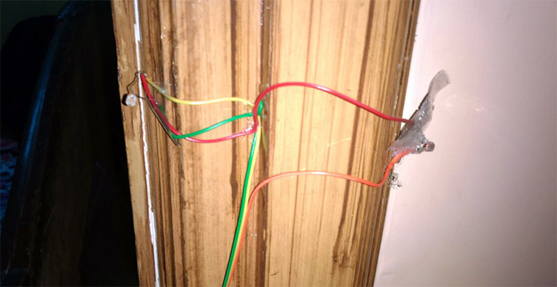
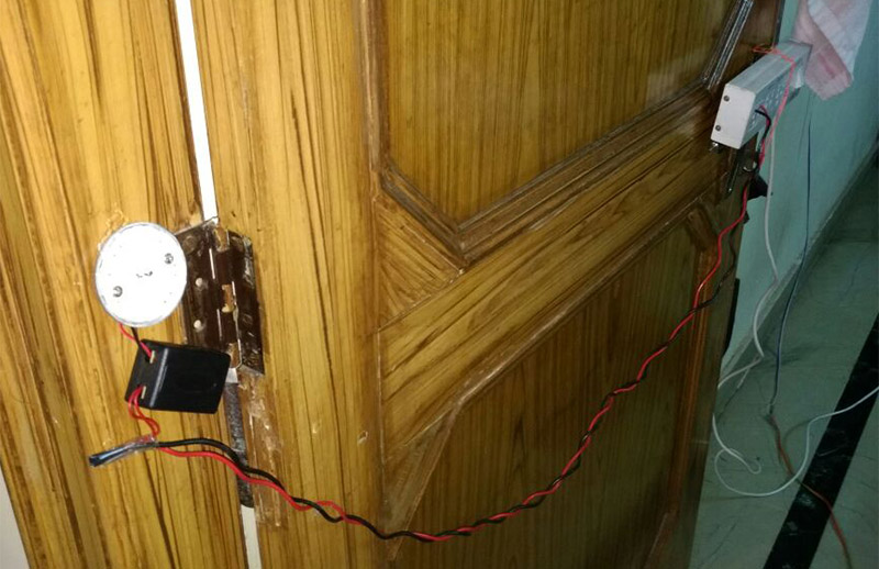
For this smart home control mount two LDR’s on the door frame of the room on one side at somewhat 120cm above floor and on the other side of the door frame light source is mounted at the same height as the ldr.
So when the person enter the room the values of resistance of first ldr changes, then of second ldr, after that value of first value revert back and second ldr follows. These series of values are interpreted by Arduino and this cycle means a person has entered room. While exiting room this cycle happens but in opposite order. This is how arduino gets how many people are there in the room.
Arduino continuously takes temperature reading from lm35 and turns fan on once temperature rise above set temp.
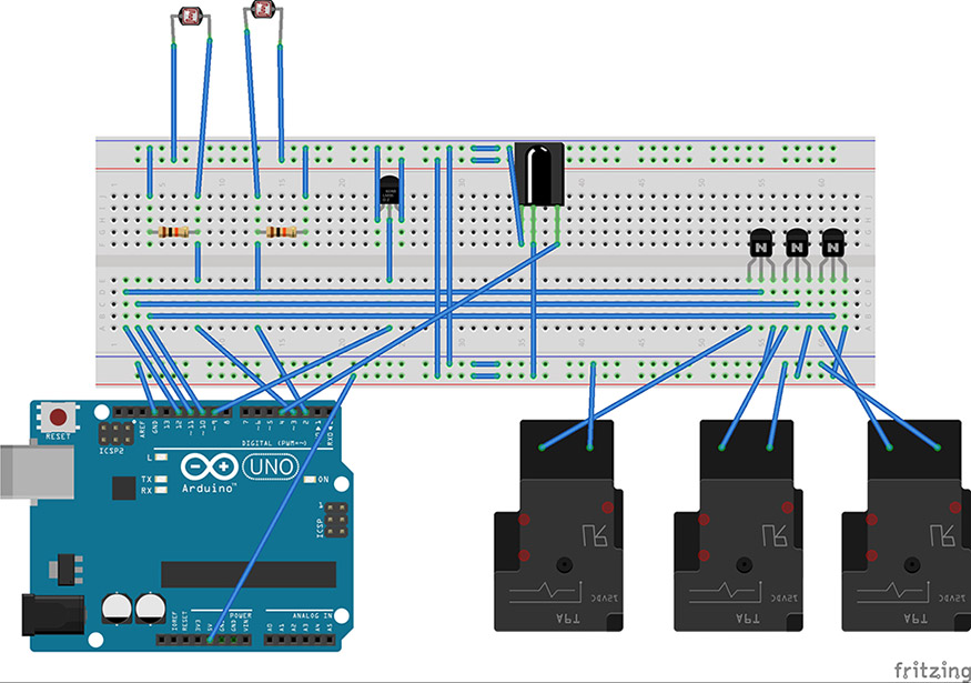
SCHEMATICS OF SMART HOME CONTROL USING ARDUINO:
SETUP:
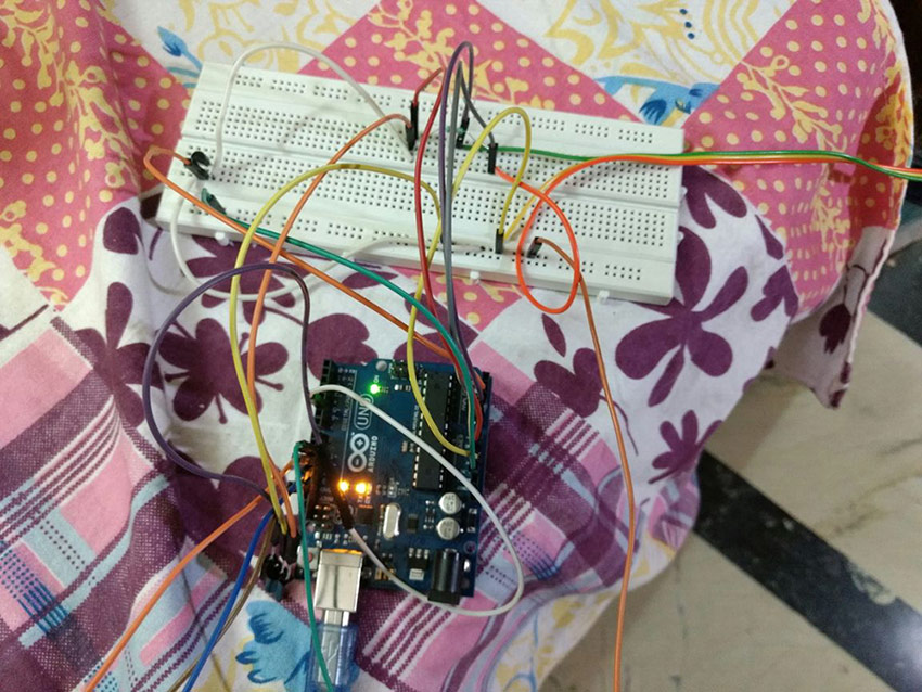
Bread boarding – Connect the Lm35 and IR Reciever according to the schematic.You may use perfboard or make your own PCB.
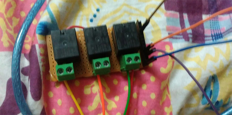
Open the Switch Board and extend the live wire as well as the wire for the appliance to the relay board and connect them to N/O and Common ff the Relays.
Connect the Relay’s coil through transistor to pin 10,11,12 of arduino.
Solder ends of ldr with long wire and wire them to the bread board according to Schematics.
Mount the Two ldr on one side of the door frame while light source on the other at same height
But make sure the light from the source falls right on the ldr.
Make all things are connected properly .Upload the sketch and you are good to go.
CODE:
//PROJECT - X SMART HOME CONTROL
//DEVELOPED BY:- UNNAT MALKOTI AND NAMAN TAYAL
#include <IRremote.h>
int RECV_PIN = 5;
IRrecv irrecv(RECV_PIN);
decode_results results;
int a=0, b=0, ldr1, ldr2, count=0, aa=0, bb=0, temp=27, tempC, reading, tempPin = A2;
boolean f=0,t=0,bulb=0,manual=0;
#define tmd 1000
void ir() {
if (irrecv.decode(&results)) {
if(results.value==0xF78877)
count++;
if(results.value==0xF7A857)
count--;
if(results.value==0xF748B7)
temp++;
if(results.value==0xF76897)
temp--;
if(results.value==0xF730CF)
bulb=!bulb;
if(results.value==0xF7B04F)
t=!t;
if(results.value==0xF7708F)
f=!f;
if(results.value==0xF728D7)
manual=!manual;
irrecv.resume(); // Receive the next value
}
}
void setup() {
Serial.begin(9600);
irrecv.enableIRIn();
pinMode(A0,INPUT);
pinMode(A1,INPUT);
pinMode(12,OUTPUT); // TUBELIGHT RELAY
pinMode(11,OUTPUT); // LED BULB RELAY
pinMode(10,OUTPUT); // FAN RELAY
digitalWrite(12,HIGH);  // LDR CALLIBRATION WHILE ROOM LIGHT IS ON
for(int i=0; i<5; i++){
a=analogRead(A0)+a;
b=analogRead(A1)+b;
delay(100);
}
a=a/5;
b=b/5;
digitalWrite(12,LOW);    // LDR CALLIBRATION WHILE ROOM LIGHT IS OFF
for(int i=0; i<5; i++){
aa=analogRead(A0)+aa;
bb=analogRead(A1)+bb;
delay(100);
}
aa=aa/5;
bb=bb/5;
}
void loop() {
if(!manual){
digitalWrite(11,bulb);
int nt=0,t=0;
ldr1=analogRead(A0);
ldr2=analogRead(A1);
t=0;
if(ldr1<a-30){   //LOGIC FOR ENTRY
while(t<=tmd){
ldr2=analogRead(A1);
t++;
delay(1);
if(ldr2<b-50){
while(nt<=tmd){
ldr2=analogRead(A1);
nt++;
delay(1);
if(ldr2>b-5){
count++;
break;
}
}
}
}
}
if(ldr2<b-50){  //LOGIC FOR EXIT
while(t<=tmd){
ldr1=analogRead(A0);
t++;
delay(1);
if(ldr1<a-40){
while(nt<=tmd){
ldr1=analogRead(A0);
nt++;
if(ldr1>a-5){
count--;
break;
}
delay(1);
}
}
}
}
if(count>0){
t=1;
digitalWrite(12,HIGH);
a=a;
}
else{
t=0;
digitalWrite(12,LOW);
a=aa;
}
reading = analogRead(tempPin); //LM35 READING ANF TEMP. CALCULATION LOGIC
tempC = (reading/1024.0)*5000;
tempC=tempC/10;
if(tempC>temp){
f=1;
digitalWrite(12,LOW);
}
else{
f=0;
digitalWrite(12,LOW);
}
}
if(manual){
digitalWrite(12,t);
digitalWrite(11,bulb);
digitalWrite(10,f);
}
ir(); //function for IR controlling
String out= "Prsn count =  ";
out+=count;
out+="    ";
out+="Threshold Temp. =";
out+=temp;
out+="    ";
out+="Current Room Temp=";
out+=tempC;
out+="       Control State :";
switch(manual){
case 1:
out+="Manual";
break;
case 0:
out+="Auto";
break;}
Serial.println(out);
}
HOW TO USE:
Remote Controller is used for system to Auto detect to Manual Mode.
While in Auto mode if a person walks into the room and last time someone was there in the room and light was on. The light will turn on. If the light was turned off manually by someone it will stay off.
If By chance the person count is wrong it can be corrected with the help of remote. By using p+/p- button for adding or reducing the person in the room.
To change the temperature above which fan turns on use button T+/T- to increase temperature or to decrease it.
While in Manual mode Fan, Tube light and Led lamp can be turned on individually by toggling buttons Fan, Tube and Bulb on the remote.
The circuit does not or you can’t find the remote turning the lights and fan on from switch board should turn them on.
PROSPECTIVE IMPROVEMENTS FOR SMART HOME CONTROL:
ESP8266 can be added for light to turn on only after sunset.
With help of relays can be triggered at or after specific time (period).
Laser should be used as light source for ldr to avoid unwanted luminance in the room.


where the program run
Hi,
Obviously on Arduino