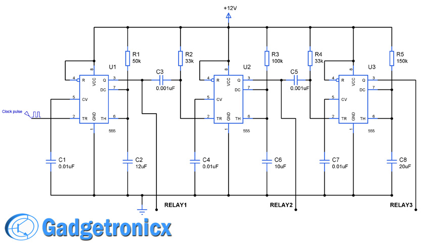
Sequential timer circuit play a significant role in all sorts of timer applications such as switching devices in sequence for a given amount and switch appliances off after desired time.This circuit explains you the how to connect a simple IC555 as a sequential timer.IC 555 holds key in designing circuits for many applications and it also enables us to design a simple sequential timer to switch three relays in a sequence.The basic principle behind this circuit was connecting the Monostable multivibrator in sequence to make it work as sequential timer.
DRIVING RELAY USING TRANSISTOR:
IC 555 is incapable of driving relay directly since the output current from a typical 555 IC is low. So we are going to use a simple transistor to switch the relay connected to it. Diode D1 was added to offer protection from the reverse current to the rest of the circuit.
WORKING:
The circuit works under a simple monostable mode connected in sequence together.As we all know that in monostable mode of operation the IC555 employs a trigger in order to switch its output states.In monostable mode operation of IC 555 whenever the input trigger given to pin 2 was high the output state of the IC remains low. But when the input goes to low state the output of the IC changes its state giving high pulse output and thus it drives the transistor to switch the relay ON to activate the device.The above circuit takes advantage of this principle too switch the devices in a sequence.In order to find more about the monostable operation of the IC 555 Click here.
As i said before the three 555 IC’s was wired as monostable multivibrator that is each needs a negative going trigger to activate the devices connected through the relay.Initailly the negative trigger from the clock source activates the first timer IC making it to give high output activating the relay.The output pin of the IC1 was connected to the trigger input of the IC2.When the high output was given by the IC1 the output of the IC2 remains in low state but as soon as the output of the IC1 becomes low, it turns the output of the IC2 into high state thereby making it to activate the second relay in sequence.In the same manner the IC3 will be activated after obtaining low output from the output pin of the IC2.
The specifications of the R and C values play a significant role in the above circuit since it decides the time period of the output.The input clock pulse also plays a vital role in switching the circuits sequentially.In the above circuit the time period of input clock signal was about 5 seconds in order to make all the three IC’s switch correctly.You should give a low-high low clock as trigger input to the pin 2 of the IC1.In the above circuit IC1 will give logic 1 for 5secs and switch off since the trigger input will be low initially for 5 seconds.Then the IC2 will give high output for 1sec and IC3 will give high output for four seconds.For this reason the input trigger was selected in means of 5 seconds time period in order to make the circuit work perfectly making to switch the relays in sequence.The output time for the IC 555 was given by the formula
hi frank,
how to determine the size of resistors and capacitors used if you want to add one more ic555 and also how to simulate this circuit in the proteus
thankyou
What kind of relay would I use? I’m looking for something that I have to push 4 12v button/switches in sequence and once the last one is pushed a final seperate 12v relay is activated and that activates the 12v motor.
Hi Frank,
Is there a unit which Would allow me to control 4 x 65Watt water pumps in a sequence i.e.:
(pump #1) 20min on then off;(pump #2) 20min on then off; (pump #3) on then off; (pump #4) on then off;
and then back to beginning
(pump #1) on then off; etc……….
and programme this easily myself ( I am not a programmer nor an electrician)
Hi Lynne,
Sorry for delayed response. For precise timings you need to seek the help of Microcontroller and probably a RTC to make it more accurate. I would suggest you to use an Arduino rather than a bare microcontroller. It’s easier to program Arduino and you will get plenty of sample code in Internet.

 Sequential timer circuit play a significant role in all sorts of timer applications such as switching devices in sequence for a given amount and switch appliances off after desired time.This circuit explains you the how to connect a simple IC555 as a sequential timer.IC 555 holds key in designing circuits for many applications and it also enables us to design a simple sequential timer to switch three relays in a sequence.The basic principle behind this circuit was connecting the Monostable multivibrator in sequence to make it work as sequential timer.
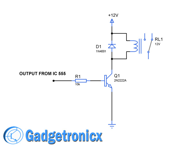 IC 555 is incapable of driving relay directly since the output current from a typical 555 IC is low. So we are going to use a simple transistor to switch the relay connected to it. Diode D1 was added to offer protection from the reverse current to the rest of the circuit.


hi frank,
how to determine the size of resistors and capacitors used if you want to add one more ic555 and also how to simulate this circuit in the proteus
thankyou
What kind of relay would I use? I’m looking for something that I have to push 4 12v button/switches in sequence and once the last one is pushed a final seperate 12v relay is activated and that activates the 12v motor.
Hi Frank,
Is there a unit which Would allow me to control 4 x 65Watt water pumps in a sequence i.e.:
(pump #1) 20min on then off;(pump #2) 20min on then off; (pump #3) on then off; (pump #4) on then off;
and then back to beginning
(pump #1) on then off; etc……….
and programme this easily myself ( I am not a programmer nor an electrician)
Hi Lynne,
Sorry for delayed response. For precise timings you need to seek the help of Microcontroller and probably a RTC to make it more accurate. I would suggest you to use an Arduino rather than a bare microcontroller. It’s easier to program Arduino and you will get plenty of sample code in Internet.
If we keep jumper to 3 outputs
It is working for total outputs
What is the problem what to do
Bhupal,
Your question is unclear, kindly explain