Vacuum Tubes are still in use even in modern times. Nowadays their purpose has shifted from audio amplification to high power RF generation, but there are still some vintage audiophile fans, who just cant quite get the tube sound out of their heads. Anyway when it comes down to the best of the best, there are a lot of factors to be considered, most of which I think I have covered here in this tube amplifier project, with just a tiny twist of modern electronics. The Amp has an automatic stand-by system, designed to preserve power when the amp is left idle for prolonged periods of time, thus extending the life span of the tubes themselves. I will cover this later on, lets first talk about the tube amplifier itself.
SPECIFICATIONS:
Input sensitivity – 20mV is the minimum signal, which will enable the automated standby system. The maximum swing depends on your source and is not critical since the amplifier has a local negative feedback, which can set the maximum levels of almost any input signal.
Output Power – 17W. According to the EL84 datasheet a push pull pentode configuration will have a maximum output power of 17W at 4% distortion.
Drawn power – 26W
Efficiency – 66% .
THD+N – Unmeasured. The power tubes are rated at 4% at 17W, and due to the many negative feedbacks employed, my guess is that the distortion value will be somewhere around 4-5%
Frequency response – Depends solely on the capabilities of the audio transformer. Mine sucks and gets saturated at around 40Hz. The upper boundary for me is around 15KHz. A high quality transformer will get a flat frequency response from 20Hz to more than 50KHz at minimal distortion.
Ripple rejection. – The most important part to not have any supply noise is the pre-amplifier, and at some extend the phase splitter. They should measure at -83dBV, which is a ripple of less than 200uV when supply ripple is 1V. The power tubes use the audio transformer as a large choke, to attenuate the ripples so there shouldn’t be a problem there.
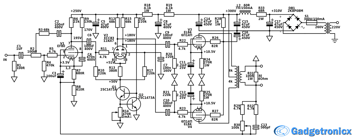
TUBE AMPLIFIER CIRCUIT:
This Tube amplifier itself is divided into several portions. Preamplifier, phase splitter, power amp, feedbacks and power supply.
PREAMPLIFIER:
The first portion of the amplifier is comprised of the EF80 tube and all the adjacent components. The tube acts as a small signal voltage preamplifier, with an adjustable gain of 2-3 times (6-9dB), by the means of R2. The tube has another very important purpose. In addition to the local negative feedback, the tube also employs a global negative feedback, which minimises distortion, flattens the bandwidth of the amplifier and stabilize the amplifier as a whole.
PHASE SPLITTER:
The second part of this tube amplifier uses a ECC83 double triode, and has a triple purpose. First it further amplifies the voltage of the input signal. It acts as a second preamplifier. Its good to somewhat distribute the gain among the stages. Secondly and most importantly, this stage acts as a phase splitter. Since tubes don’t come in complementary pairs as transistors do, its essential to drive the push pull power stage in anti-phase. When one stage increases conduction, the other should decrease its conduction ideally by the same amount. This can only be accomplished with anti phased inputs. For best symmetry, i have used a constant current sink in the cathode chain, comprised with the only two transistors in the circuit, because although its simpler to use transistors instead of tubes for this purpose, it even works better, since tubes act erratic under 70V or so, while transistors work well, down to much much lower voltages. This brings us to the third purpose of this stage. It acts as a driver stage for the power amplifier. Instead of loading down the first stage, which should be as linear as possible, a buffer stage can separate it from the power amp and handle the load better.
POWER AMPLIFIER:
The third part of the schematic is the power stage. Its really nothing fancy, I basically used the datasheet to figure out the details around it, since power tubes are costly and don’t work well with design improvisation. So its a simple push pull stage in pentode mode, which gives highest output power levels and still gives decent linearity. The audio transformer has an 8k a-a primary impedance and works as an impedance matching device, where the high impedance output of the tubes, needs to be matched to the low impedance speaker.
The next part is not so obvious at first sight, because it appears at multiple places in the schematic, and thats the feedbacks. To get the first stage working as linearly as possible, I employed a local negative feedback from the plate, to the input grid. This way the gain gets restricted to around 2-3 times and the output becomes much more linear. The second feedback is global, and can be clearly seen from the output of the circuit, to the cathode of the EF80 tube. A global feedback stabilizes the amplifier as a whole, flattens the frequency response, and further reduces the distortion. There is also a frequency dependent negative feedback, restricting the bandwidth of the amplifier, keeping it away from the audio transformer`s self resonance frequency.
POWER SUPPLY FOR TUBE AMPLIFIER:
The last part and probably the hardest to get right for this tube amplifier project is the power supply. The power supply itself is nothing fancy, just a bridge rectifier and a smoothing LC Pi filter, but the trick to get it right is really by experimentation. The transformer you have may be weak, and may drop more voltage than the one I have, so whatever works for me might not work for you. I recommend starting with this topology and taking it from there. Just experiment with your transformer. If you get higher voltages, just add a bigger resistor across the LC filter and vice versa. Just make sure you don’t exclude the resistor altogether, because the Pi filter may start ringing and may expose the tubes to higher voltages. The way I designed it the critical dampening frequency is around 10Hz, which is more or less out of the audible range, thus it wont be triggered to ring by the amplifier.
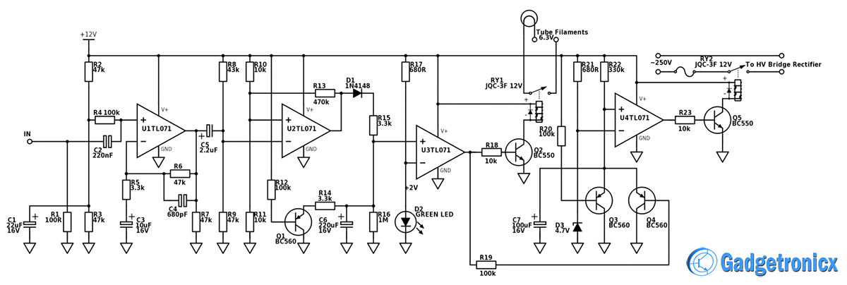
The second major part of the circuit is the automatic stand-by system. I’m gonna go through it step by step, but lets first explain its purpose. The circuit is designed to not allow the tubes to be exposed to excessive voltages while still cold. This will increase their lifespan and make sure they wont degrade as fast. Also the circuit minimizes power consumption when the amplifier is left idle, by sensing whether there is an input signal and acting accordingly. Lets get to the circuit.
As you may see this circuit has nothing to do with tubes. It uses discrete, ICs and relays to get things done. The first op amp works as a voltage amplifier. It amplifies the input signal to reasonable levels, where the other parts of the circuit may work reliably. The minimal threshold level of the stand-by system is set to 20mV. When there is an input signal higher than the threshold, the second op amp (working as a schmitt trigger) starts shaping output pulses, that charge the 220uF capacitor to a given value.
The schmitt trigger makes sure, that once the threshold is reached the output will always be a pulse, and not some distorted and amplified version of the wave. Once the capacitor reaches a threshold level of 2V, set by the LED, the third op amp will change states and shape a high level voltage on the output. This will enable Q2 and the RY1 relay, and the tube filaments will start getting energized, during which Q4 will disable, and this will allow C7 to start getting charged. When C7 gets charged to 4.7V, set by the zener D3, the fourth op amp will enable the Q5 transistor and the RY2 relay, thus exposing the tubes to the HV rail.
This will happen in roughly 16s after the tube filaments get energized, giving them time to start up the thermionic emission of the tubes, thus not exposing a cold cathode to such high voltages. When you disable the input signal, the second op amp will stop charging the C6 cap, and it will start discharging through R16. In around 16 minutes, the voltage will discharge below the third op amps threshold level, thus disabling the heater filaments, and enabling Q4. C7 will discharge through Q4 and the HV rail will become disabled, thus setting the amplifier in a standby mode.
Hello, Im amazed how well the circuit is designed, but i have few questions.
What is the purpose of R14,S1 and R31. Also is it possible to use an output transformer with pri: 8k CT and sec: 8ohm? Thanks in advance!


Hello, Im amazed how well the circuit is designed, but i have few questions.
What is the purpose of R14,S1 and R31. Also is it possible to use an output transformer with pri: 8k CT and sec: 8ohm? Thanks in advance!