Musical greeting cards are quite popular during special occasions all around the world and we all would have presented this thing to our dear ones before. But have you ever tried making one by your own? if not, its time to build one. Here is a simple Musical greeting circuit you can try out easily in your home, also the cost required to build this thing is pretty low.
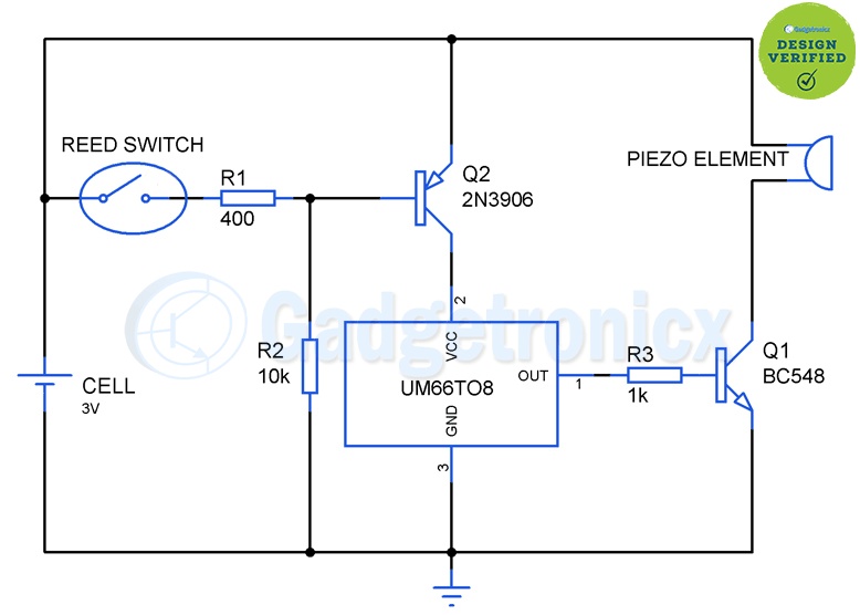
CIRCUIT DIAGRAM:
UM66TXX SERIES IC’s:
The UM66TXX is a simple CMOS IC which was designed specifically to be used in this kind of simple melody/tone generation circuits. It consists of a on chip ROM programmed with particular music or tone and named based on the tone. Since it was produced by using CMOS technology it consumes only less power which proves to be a great advantage. Here is the list of IC’s with programmed tones.
UM66T01 – Jingle bells + Santa is coming to town + We wish you a merry xmas
UM66T02 – Jingle Bells
UM66T04 – Jingle Bells + Rudolph the red nosed reindeer + Joy to the world
UM66T05 – Home sweet home
UM66T06 – Let me call you Sweetheart
UM66T08 – Happy Birthday to you
UM66T09 – Wedding march
UM66T11 – Love Me Tender, Love me True
UM66T13 – Easter Paradise
UM66T19 – For Elise
UM66T32 – Waltz
UM66T33 – Mary Had a little Lamb
UM66T34 – The train is Running fast UM66T68
USE OF REED SWITCH:
You might have seen that musical greeting card uses leaf or slider switch which activates the toner when you open it. The major problem with those type of switches is that the link gets weaker with time due to usage and gradually the circuit gets activated even when the card is in closed position. This will be annoying most of the times.
To overcome the above drawback reed switch was used here which uses magnetic force for activation. So there won’t be any undesirable activation of the tone generator part in our circuit. Place a magnet in one side of the card and the rest of the circuit in opposite side. Make sure that magnet touches the reed switch when the card is closed.
WORKING OF CIRCUIT:
The working of the circuit begins with the Reed switch which gets activated whenever it comes in contact with a magnet. Affix the magnet in one side of the card and the entire circuit is other side of your card. When the card was in closed state, reed switch will be in closed state and this makes the base of the PNP transistor to be in positive potential i.e more than 0.7 v which forces it to off state.
Opening of the card will force the magnet to break its force of attraction and the reed switch will be in open state now. Then the resistor R2 will pull the base to ground potential. This makes the PNP transistor Q2 2N3906 to switch on and this in turn turns the IC UM66T08 on.
When the IC is turned on The output of IC was fed in to the base of the NPN transistor Q1 and this supplies the required current for the sounding element to operate. Finally we can get our desired tone/melody from the piezo sounder. In the above circuit IC UM66T08 was used which contains “Happy Birthday to you” tone programmed within it.
NOTE:
You can use the primitive leaf or slider switch with the above circuit instead of reed switch, in that case eliminate R1,R2 and Q2 and connect the switch end directly to the VCC pin of the IC.
Make sure that the magnet and switch was placed in such a way that it touches each other when the card is closed.
The above circuit generates “Happy Birthday tone”, however if you need any other tone choose the respective UM66TXX IC from the above given list.