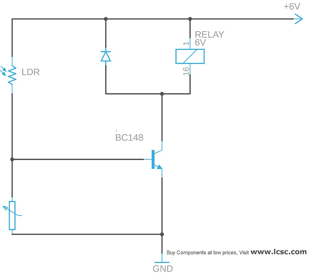
This is a simple light sensor circuit diagram which activates a relay when Light incident on sensor is above threshold.This circuit cost less. It comprises of a transistor, potentiometer, LDR(Light Dependent Resistor) and a relay with a protection diode.
WORKING OF LIGHT SENSOR CIRCUIT DIAGRAM:
The working of this circuit is very simple and uses only less components in it. This simple circuit using a single transistor turns the relay ON when light falls on LDR. The Light Dependent resistor exhibits low resistance when light falls on it and high resistance when light is obstructed or very less intense light falls on it.
The potentiometer can be used to adjust the sensitivity and setting light threshold for this circuit. And a relay is used to activate any devices or appliances when light exceeds the preset threshold. Use a diode with this relay which protects the other electronic components from the brief high voltage produced when a relay coil is switched off.
When light falls on the LDR its resistance is low therefore the transistor enters into saturation state and turns the relay circuit on. When the light is obstructed LDR offers a high resistance to the current flow thus the potentiometer shorts the transistors base to the ground and it is cut off.Hence this makes the relay off.Thus we can detect the falling of light on any object.
I am building a chicken coop with an automatic door that opens at sun up
and closes at sun down. For power I will have a solar panel charging a 12
volt auto battery. Can your circuit run on a 12 volt battery?
Add a 56 ohm 2 watt resistor in the 6v feed. This will bring the voltage down to about 8 volts when the transistor is off and to about 6 \volts when the transistor is on. That should work perfectly in a 12 volt circuit


Does it matter if the 10k pot is logarithmic or linear?
I am building a chicken coop with an automatic door that opens at sun up
and closes at sun down. For power I will have a solar panel charging a 12
volt auto battery. Can your circuit run on a 12 volt battery?
Hi Don,
Ya it will not a problem 🙂
Add a 56 ohm 2 watt resistor in the 6v feed. This will bring the voltage down to about 8 volts when the transistor is off and to about 6 \volts when the transistor is on. That should work perfectly in a 12 volt circuit