Timer IC 555 is not dead yet, this is because of the extended functionalities it provides at a low cost. Be it an Oscillator, Timer or Trigger this chip can do a fine job. In this article we are going to see how to build a Light that is capable of adjusting its brightness based on the atmospheric conditions. To put it other way, this LED beacon will light up brightly in the dark whereas in presence of daylight it will off or produce minimal light.
CONCEPT:
This circuit uses the PWM capability of IC 555. For those who don’t know PWM is a technique where OFF and ON times of a pulse is altered. This is mainly used for controlling speed of a motor, intensity of lights and save power consumption.
Here in this circuit we are going to use PWM to control the intensity of light. And to do this we are going to generate a high frequency square wave and modify it’s mark and space ratio or ON/OFF times. Increasing the ON time of a pulse in this high frequency signal will increase the brightness of the lights whereas increasing the OFF time will decrease the brightness of our light.
MEASURING THE RESISTANCE OF YOUR LDR:
Measure the resistance of your LDR under various light conditions. This is important since resistance greatly differs with different manufacturers. So I have measured the resistance of my LDR under various light conditions ( just a rough measurement to choose the capacitor and resistor values in the circuit) and noted in the below table.
Light Conditions
Resistance in Ohms
Lighting up using torch ( high intensity light)
400
Inside room (daylight)
10k
Under Artificial light
22k
Under poor light conditions
150k
Pitch dark
170k
Remember the above tabulation is made roughly to for calibration as mentioned earlier. However if you need to do it very accurately you may need to measure the light intensity in Lumens using Luxmeter and then tabulate it against the corresponding LDR resistance. In my opinion that high level of accuracy is not necessary for this project so I kept it simple.
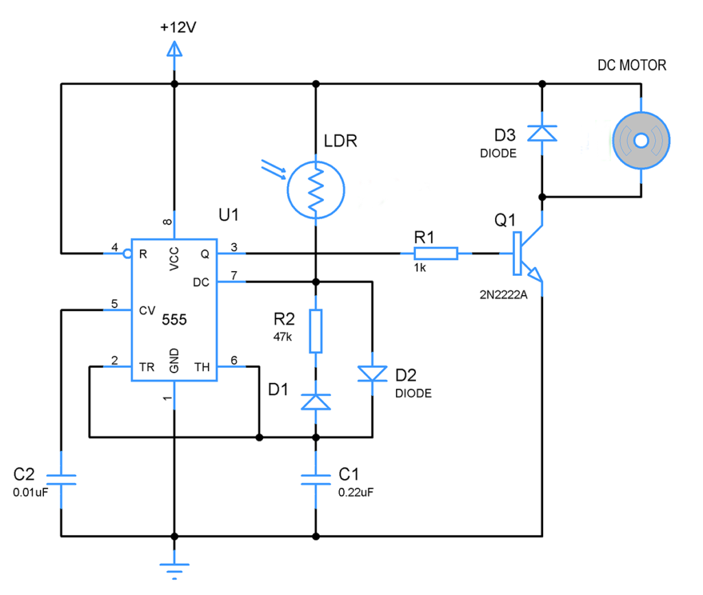
To understand the above circuit it is good to have a read on working of “Timer IC 555”. Here in this circuit this IC is wired to function as an astable multivibrator to generate a series of square wave pulses. The generation of this square wave pulse depends upon the voltage in two pins “Threshold/ 6th pin” and “Trigger/ 2nd pin” of IC 555. The output will be high until voltage in threshold pin reaches +⅔ of supplied VCC and will switch to low once it hits the mark. The low state will remain until the voltage in trigger pin falls below +⅓ of supplied VCC.
As you can see in the above circuit these two pins are connected to positive terminal of capacitor. So in a sense the output state of IC 555 depends on the voltage exhibited across the capacitor. When the system turned ON capacitor C1 will start charging via LDR and Diode D1. As we know resistance in LDR decreases with increase in intensity of incident light. So during day or in great light conditions the resistance of LDR will be low which in turn allow capacitor to charge quickly to the point of +⅔ Vcc.
The resistor R1 will not play a hand while charging the capacitor due to the restrictions posed by Diode D2 to the current flow. Once the capacitor voltage hits the +2/3 Vcc mark output switches to low which in turn activates the internal discharge transistor in pin 7. Now the capacitor discharges through the resistor R1 and the voltage across capacitor starts to drop. The low state in output will remain until the cap voltage reaches the +1/3 Vcc after it will switch back to high state. This will turn off the discharge transistor and the whole cycle repeats itself.
LED BEACON:
This section is pretty much very simple with generated PWM signal fed to base of transistor and drive the LED’s connected to its collector terminal. Transistor base will be activated by means of this PWM signal and LED’s will be activated during the ON time period of the signal. LED being a slow component when driven by a PWM signal of higher frequency will exhibit a continuous lighting or non lighting effect as output. And there you have your light responsive LED beacon. The LED’s will consume about 60mA of current. You could increase the number of LED’s to make even powerful LED beacon.
CALCULATION:
Here is a brief explanation on calculation behind this circuit. We need to fix the values of R1 and C1 since values of these components decides the frequency and Off time of PWM pulse in the output. We need a high frequency pulse in order to avoid flickers in output. Lesser the capacitance, faster the charging and discharging cycle of capacitor. So I have chosen
C1 = 0.22uF
I need the beacon to produce a fading effect in LED beacon based on the incident light. So I need to choose a resistance value which lies somewhere between these conditions “Under Artificial light” & “Under poor light conditions” so I choose 47K which will give a good balance between ON and OFF period of PWM pulse, thus creating a smooth fading effect.
To determine the ON and OFF time various conditions we use the below formula T1 = ON time , T2= OFF time
T1 = 0.693 x LDRres x C1
T2 = 0.693 x R1 x C1
Using the above formula to calculate the Time period, Duty cycle and Frequency
i ) Lighting up using torch ( high intensity light)
LDRres = 400 ohms
T1 = 0.693 x 400 x 0.22uF
= 0.000069 sec
T2 = 0.693 x 47k x 0.22uF
= 0.0072 sec
To calculate frequency of PWM wave
Ttotal = T1 + T2 = 0.000069 + 0.0072 = 0.0073
F = 1 / 0.0073 = 137Hz
Duty Cycle = LDRres / LDRres + R1
= 400 / 400 + 47K
= 0.84 %
So as you see above when the light in the surrounding is very high ON time is very low as 0.84% hence the LED will be in very dim state.
ii) Pitch dark
LDRres = 170k
T1 = 0.693 x 170k x 0.22uF = 0.025
T2 = 0.693 x 47k x 0.22uF = 0.007
F = 1 / 0.032 = 31.25 hz
Duty Cycle = 170k / 170k + 47k = 78.3%
The above two conditions are two extremes and as you can observe in calculations, the circuit does a fairly good job in brightening and dimming under different light conditions.
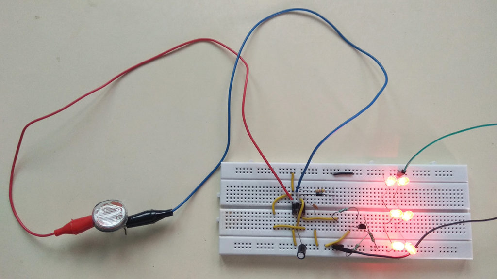
REPLACING THE LED BEACON WITH A DC FAN:
You could try out another variant of this circuit by replacing the LED’s with a DC fan. The circuit will work in similar nature and control the speed of DC fan based on the intensity of light incident on LDR. Fan will run faster when light intensity is less and slower when the intensity is high.
You could also use other Photo conductive components like thermistor to make this project responsive for temperature. Hope you guys like this project, do try this out and let me know the outcome. Thank you, Happy making 🙂