LED’s we can never get enough out of this thing. I am always fond of building projects and playing with LED’s because of their vibrant colors and unending possibilities. I got the idea of writing a tutorial on interfacing RGB led with Arduino to help those who are not aware of interfacing and programming them.
RGB LED:
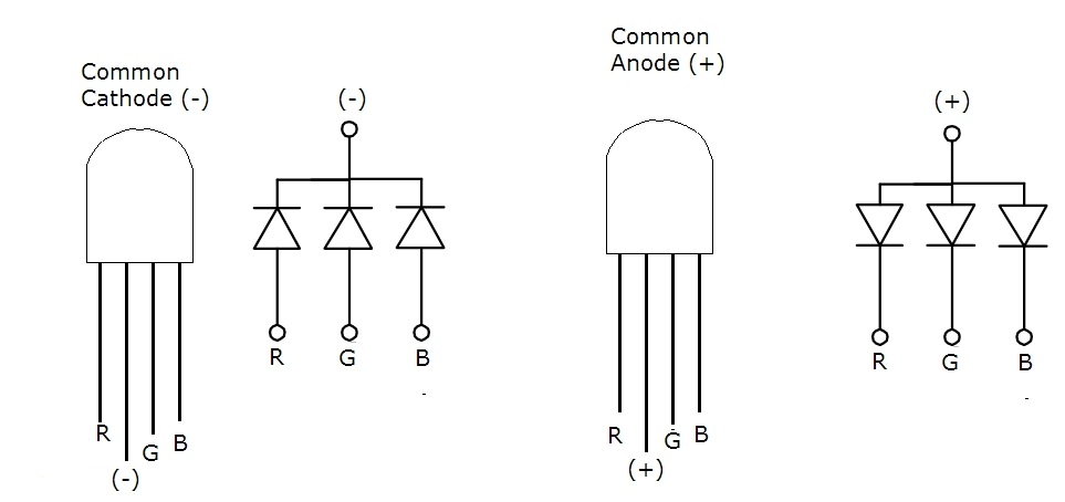
This is nothing but LED’s of three colors Red, Blue and Green combined together in a single package with a pin dedicated to each color and one pin as common. Altogether this LED will have 4 pins in total as shown above.
TYPES OF RGB LED:
There are two types of RGB LED. Unlike the 7 segment display there are Common Anode and Common cathode LED’s as shown in the above figure. In Common Cathode configuration RGB pins are used to source the voltage from Arduino and common pin is meant to sink the current, resulting in lighting up the desired color . However in Common Anode configuration Common pin is to source the voltage and desired color can be lighten up by sinking the current through pins of Arduino or any other controller.
WIRING DIAGRAM:
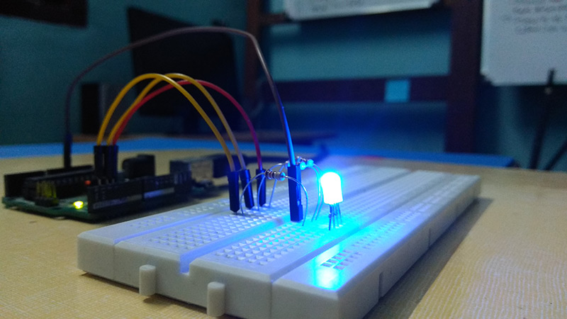
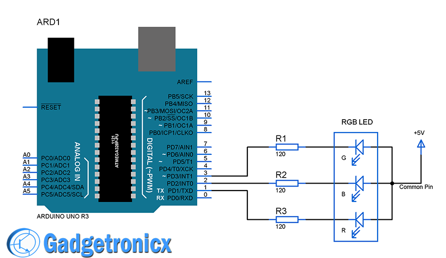
I have used common Anode RGB LED to illustrate in this tutorial. As explained in the above section for a Common Anode LED current from Common pin should be sinked to the pins of Arduino via R, B and G pins. So in order to do that I have used digital pins 1,2 and 3 of Arduino. You must add a resistors to each pins RGB in order to limit the current flow through it.
Digital pins 1,2 and 3 are used to interface LED with Arduino. As you can see in the line 16, 19 and 22 of the above code you will notice I have made the pins LOW in order to light up the corresponding color. I have built the code in such a way each color cycles infinitely with 3 second duration.
Hope this tutorial is of much help to you. Love to see what you guys make out of RGB LED’s. If you have any queries or feedback do post it in the below comment box and I will be happy to write back to you 🙂


 using LED's")

