Infrared sensors have wide variety of applications ranging from robotics and automation. IR sensors have been doing quite a great job in all these applications for many decades. This article teaches you to build a simple Infrared sensor module circuit which can be used with any application which needs detection or sensing.
INFRARED SENSOR MODULE CIRCUIT DESIGN:
WORKING:
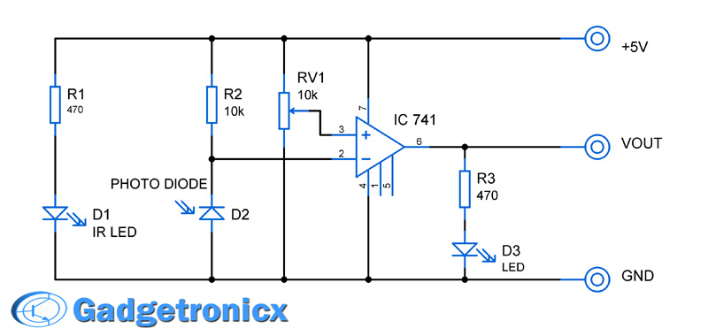
A simple IR led and Photodiode used for emitting and sensing the IR beam. And Op Amp IC 741 is used as an comparator which in turn switches the output level as either logic 1 or logic 0. The Variable resistor RV1 used to tune the sensitivity of the detector by altering the reference voltage to the comparator. And at last LED D3 was meant as an indicator in case a IR beam is detected or reflected.
When the circuit is powered IR LED D1 emits Infra red beam. The photodiode D2 was connected in a reverse biased manner along with a resistor R2 in series. When there is no IR beam incident in the photodiode no current passes through it which in turn leads to no drop in voltage and inverting terminal of the Op Amp is fed with max voltage that is 5V. Since the voltage in the inverting terminal is more than the reference voltage at the “+” terminal of op amp the output stays LOW or logic 0.
When IR beam is reflected by any body which makes the beam to incident on Photo diode, current passes through it and in turn a drop of voltage occurs between the terminals. Now the reference voltage at the + terminal of Op amp is more than the – terminal. The output of Op amp switches to high or Logic 1 state.
This module will be highly useful to interface with Microcontroller for sensing since it provides the output in two logic levels which is compatible many microcontrollers.


What is the role of resistance R2?