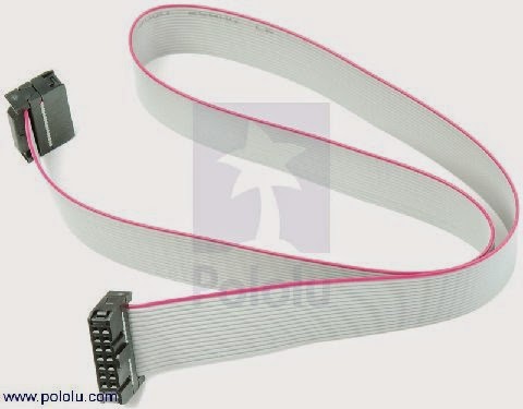
IDC ribbon cable tester circuit is designed to check IDC (Insulation Displacement Connection) cables quickly for shorts to adjacent pins or opens from one end to the other. Originally, I designed this unit to test ribbon cables used on test equipment in the automotive industry. But it works for any ribbon cable. There are multiple types of sockets used with ribbon cables.
CIRCUIT DIAGRAM:
The most common are dual row headers (both male and female) and “D” type connectors (both male and female). If you build the tester and include two sets of 40-pin dual row headers (M&F) and “D” type (M&F) for the “O” port, and the “N” port, you should be able to test most types of ribbon cables. There are “.1” and “2” mm spacings too. Wire the four “O” headers and “D” ‘s in parallel and the “N” headers and “D” ‘s in parallel. This will allow the user to test male to female, male to male, female to female and female to male cables all on the same unit.
WORKING OF IDC RIBBON CABLE TESTER:
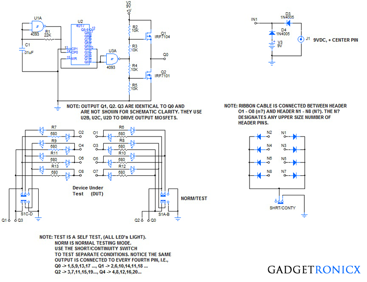
The heart of the Ribbon Cable Tester is the clock, U1A, (CD4093 schmitt NAND), R8, C1, they feed the clock pulses to the CP0 input of the U2 (CD4017 sequential decade counter). The outputs of U2 turn ON individually and sequentially with each rising edge clock pulse. After the fourth clock pulse, Q3 of U2, turns OFF, and Q4 turns ON. This resets U2 causing Q0 to turn ON, to continue the four step pattern. When U2, Q0 is (high, 1), the output of U3A is (low, 0), which turns transistor Q2 OFF and Q1 ON and makes output Q0 = (high, 1).
When U2 Q0 is (low, 0), the output of U3A is (high, 1), which turns transistor Q1 OFF and Q2 ON and makes output Q0 = (low, 0). So each time an output of the CD4017 goes (high, 1), so does the drive voltage of the corresponding output go (high, 1). U3A, plus transistors Q1 and Q2 form a power buffer to drive the LED matrix.
When output Q0 is (high, 1), current is able to flow through R6, and the LED to O1. When the Short/Continuity switch is in the continuity position, the O1 green LED will light if the path from O1 to N1 is correct. This applies for all of the corresponding On to Nn connections. When the Short/Continuity switch is in the short position, no LED’s will light unless there is a short to an adjacent wire, such as wire O1 to O2, or O3 to O4 etc.
Using the first example, a short between O1 and O2 would cause the green O1 LED and the red O2 Led to light when output Q0 was ON, and would cause the green O2 LED and the red O1 LED to light when the Q1 output is ON. This would show the user that the short in the cable is between conductor 1 and conductor two. This could be from improper clamping of the IDC header on the cable, or faulty insulation between conductors, or a foreign object wedged into the ribbon cable between conductors. Whatever the reason, the Ribbon Cable Tester will find the problem.
The Normal/Test switch allows the user to test the unit to make sure everything is working properly. When the switch is in the Test position, all of the LED’s light to show that the clock, counter, buffers and wiring is in good shape. In the Normal position, the unit is ready for testing ribbon cables for continuity and shorts. This is a really good device if you have a number of ribbon cables that need testing.
Hi Bruce, The schematic shows only the first of four outputs connected to Q0 of the CD4017 counter. By connecting the next three identical outputs, consisting of the a 4093 gate and the resistors and MOSFETs, to Q1, Q2, and Q3 of the 4017, each IDC pin, 1, 2, 3, 4, will be energized in sequence. By wiring IDC pins 1, 5, 9, 13, 17, 21, 25, 29, 33, etc… to the Q0 output, wiring IDC pins 2, 6, 10,14,18, 22, 26, 30, 34, etc…. to the Q1 output, wiring IDC pins 3, 7, 11, 15, 19, 23, 27, 31, 35, etc….. to the Q2 output, wiring IDC pins 4, 8, 12, 16, 20, 24, 28, 32, 36, etc….. to the Q3 output, you will have a repeating sequence for alll the IDC pins. The adjacent shorts or opens will be identified. I hope this explanation clarifies the schematic drawing. It showed only one output driver circuit to simplify the drawing.
A friend and I maintain several installations for non-profits that use 26 conductor ribbon cables, standard female 2 row connectors each end. We are looking for an inexpensive tester to test continuity/adjacent shorts. We would like to buy one ready built, would only need a pair of male sockets to connect the cables. Do you build and sell any, or could you email information of a source? Don’t need to use with any other pin counts or connectors.
Thanks!
I am looking at building the IDC ribbon cable tester. I am confused about the counter — it appears to me every “1” on the counter will light LEDs every four positions. i.e 1,5,9,13… Is that correct?