LED lighting have a great demand since it consumes less power also have a increased life time. Also LED allows us to build beautiful lighting Circuit than the normal ones. Here is a similar lighting circuit which uses the concept of PWM to alter the LED lighting rate which in turn gives multiple lighting effects and be used to decorate your home.
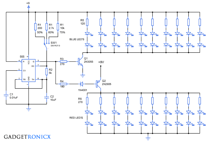
CIRCUIT DIAGRAM:
WORKING OF CIRCUIT LIGHTING CIRCUIT:
555 Timer IC forms the center piece which was wired as a simple astable multivibrator in the above circuit. We all are aware that the astable mutivibrator gives out square pulse as output. The frequency, time period and duty cycle of the pulse was decided by the three Key components R1, R2 and C2. These components affects the capacitor charging rate and time taken to switch output states in a timer IC.
 |
| PWM signal |
This is where the PWM is employed which alters the duty cycle of the output pulse. Duty cycle defined as the time period in which the signal is active, expressed in percentage (%). Altering the duty cycle will provide variation in LED on times and this provides a beautiful lighting effect. The duty cycle of the 555 was governed by the equation
Duty Cycle = (R1+R2) / (R1+2R2) %
The above circuit was provided with a simple single pole triple throw rotary switches which allow us to alter the duty cycle with ease. According to the equation given above the R1 and R2 decides the duty cycle fatcor in the outout pulse. So when R1=200 ohm and R2=5K the duty cycle will be
Duty cycle = (200+5K)/(200+2(5K))= 50 %
Likewise 2.7K and 10K of R1 will result in 60 and 70 percentage of duty cycle. Capacitor C2 can be changed if you need to alter the frequency of the output waveform.
Next comes the lighting stage, the output of the 555 is not enough to drive many LED’s to produce the lighting. So transistors was used as a switch to turn ON the LED’s connected to it. Two transistors NPN and PNP was used in the above circuit to make the lighting effect even cooler.
The NPN transistor & the LED’s connected to it turns on whenever there is a high pulse from the 555 and it will stay on as long as the high pulse remains. And when the 555 switches its state to low the transistor Q1 and led’s connected to it turns off but PNP transistor Q2 and led’s connected to it gets lighten up producing a beautiful lighting effect.
The circuit is capable of producing effects like wave, disco and lots more. Try wiring the LED’s in different patterns to get even cooler lighting effects.
NOTE:
- You can increase add or change resistors R1 based on the calculations to obtain altered duty cycle in the output.
- Additional capacitors C2 and rotary switches can be added to get altered frequency in the output.
- Multiple combination of LED’s can be used in the above circuit.


cahit aydın şebekeden beslense iyi olurdu
English please.
can you provide me with the pdf explaining all about it?