FG’s are quite expensive in nature and not many could afford one for their experimentation and learning. This circuit design might come in handy for those who want to build a efficient FG of their own. This DIY function generator is the deluxe version of Function generator Circuit published on our site few days ago. This Function generator circuit built around quad opamp MCP6024 comes with added features such as adjustable and selectable Sawtooth waveform generation, selectable frequency ranges, output waveform selector switch and frequency counter oscilloscope trigger output. The output of this FG ranges from 30 seconds to 350 Khz.
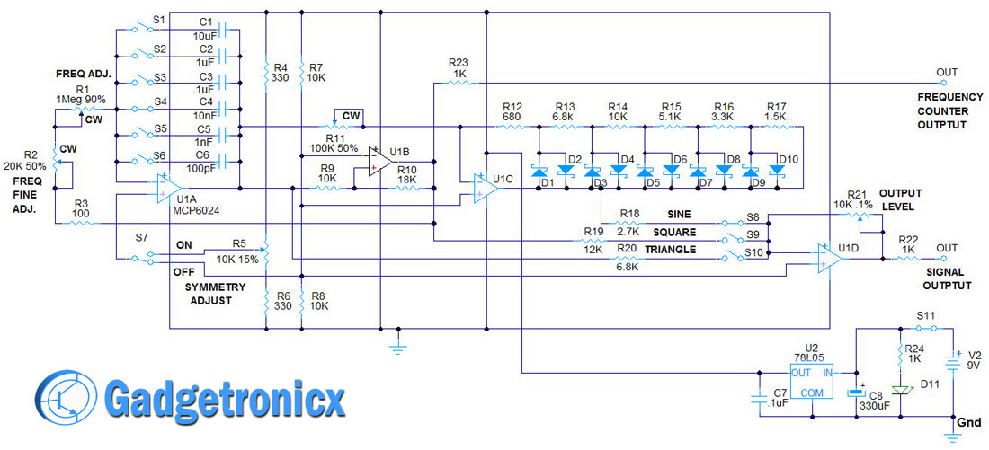
CIRCUIT DIAGRAM:
WORKING OF FUNCTION GENERATOR CIRCUIT:
The heart of the function generator is the integrator, formed by U1A( IC MCP6024), R1, R2, S1- 6, C1 – 6, and the comparator with hysteresis, formed by U1B, R7, R8, R9, and R10. They work together in the following way. U1B has it’s output low, when the input feeding U1Ain- is less than the reference voltage, the output of U1A ramps up.
The output of U1A goes through R9 to input U1Bin+. When the voltage at U1Bin+ is greater than the reference voltage at U1Bin-, (half of the supply voltage), the output of U1B goes high. This raises the voltage at U1Bin+ causing U1B to switch states. Since the output of U1B is higher than the reference voltage at U1Ain+, the output of U1A begins to ramp down. When the output of U1A through R9 pulls the input U1Bin+ lower than U1Bin- reference, U1B output switches low. This causes U1A to again begin ramping up until the output of U1A causes the input U1Bin+ to go higher than U1Bin-, and the process repeats in an oscillating manner.
The output of U1A is a triangle wave. The output of U1B is a square wave. To produce a pseudo-sine wave, the output of U1A is connected by R11 to input U1Cin-. The network of resistors R12 – R17 and diodes D1 – D10 clip or reduce the gain of U1C progressively, as the triangle amplitude increases. This reduces and rounds off the tip of the triangle wave to produce the pseudo-sine wave. Diodes D1 – D10 are 1N34 germanium diodes. They were chosen for their lower forward voltage drop, (.35 volts), compared with silicon, (.6 volts).
The outputs of U1A, U1B and U1C are connected through R18, R19, and R20 to the input U1Din-. R21, a 10K potentiometer, provides the appropriate feedback to control the output level of U1D, from 0 to Vmax. A selector switches S8-10 is used to select the desired output type of waveform. Switches S1-S6 , selects different values of capacitance C1 to C6, to change the frequency range of the function generator.
Switch, S7, connects integrator input U1Ain+ to either +V/2 at the junction of R7 and R8, or the wiper of R5 which can be adjusted to nearly +5V or ground to create a saw tooth wave at the output of the integrator U1A. R23 is used to protect the output of U1B while providing an output signal to an external frequency counter or oscilloscope trigger. R2 is used to make a fine frequency adjustment in the output which will be handy in several situations.
OUTPUT WAVEFORMS:
Output waveforms of the FG circuit
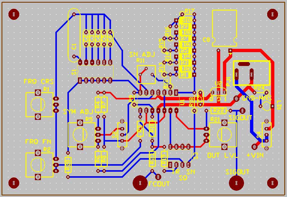
PCB DESIGN:
You can Download the Gerber files of the above Design below.
Selector switch S1 to S6 is used to select the frequency ranges of the output.
S7 lets the user to select 50% symmetry or adjustable symmetry to generate Sawtooth Waves.
S8,S9 and S10 switches are used to select the required waveform (Sine, Square or Triangle).
The integrity of the output waveform is excellent up to 200khz.
Quad Op-amp IC MCP6024 is a Quad RRIO (Rail to Rail, Input Output) Op-amp with 7v/uS Slew rate,10MHz BW and the power supply must be less than 5.5 Volts.
Hi Rafay, I am not familiar with the mc34074 quad op-amp. The MCP6024 was selected because it has a high slew rate 10V/usec and therefore a high bandwidth. Additionally, the inputs have little temperature drift, and the input bias currents are extremely low. If you can find another op-amp with similar specs use it. You must compare the data sheet for the two parts to determine if the substitution can be made. Though the MCP6024 might cost a little more, the faster slew rate and low bias currents are worth the price. Hope this helps and good luck with your build. Ron


 You can Download the Gerber files of the above Design below.


Can i replace mcp6024 with mc34074 if yes then how and if not then kindly tell me the replacement of mcp6024 waiting for your reply
Hi Rafay, I am not familiar with the mc34074 quad op-amp. The MCP6024 was selected because it has a high slew rate 10V/usec and therefore a high bandwidth. Additionally, the inputs have little temperature drift, and the input bias currents are extremely low. If you can find another op-amp with similar specs use it. You must compare the data sheet for the two parts to determine if the substitution can be made. Though the MCP6024 might cost a little more, the faster slew rate and low bias currents are worth the price. Hope this helps and good luck with your build. Ron
i can’t download the PCB file i am doing this as a Student project.
Hi DJ, Hope you received my e-mail. Did that help you to solve your problem? Please advise. Ron H.
Djmkeace,
Sorry for the delay, you can now find the gerber files from the article now.
I’ll be definitely be making this
Milos, I hope the board layout and BOM helps you with your build. It works really well. Ron H.
Did you build it yet? How did it turn out?
Milos, did you build the FG yet?