This is a very simple circuit which was used to detect the Electromagnetic field which was around us.The principle behind this circuit was mutual induction whenever a EMF was near a inductor mutual inductance takes place and due to this mutual induction it results in a voltage in the inductor.Using this induced voltage the EMF field was detected.Lets see the working of emf sensor circuit.
WORKING OF EMF SENSOR CIRCUIT:
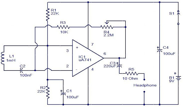
As said above here a 1mH inductor was used as a sensing element for this circuit to detect the EMF.Whenever the inductor was near the EMF field a voltage was induced in it.But the voltage induced due to the EMF field was very less so it needs to be amplified before going into the next stage.Here the most common IC uA741(Op-Amp) was used as Amplifier to increase the strength of the voltage.9V battery was used to power the circuit and a switch was provided to make the device on or off.
The input of the wired amplifier was given to the terminal 3&2 which is inverting and non inverting terminal of the amplifier.The output voltage will be amplified and was obtained from the 6th pin.A simple variable resistor is connected to the output 6th pin which was used to adjust the gain of the amplifier.And finally the output was given to a headphone whenever the inductor senses a EMF field it was heard as a hum sound in the headphone.The headphone can aslo be replaced with devices like voltmeter to detect the EMF field.In order to make the circuit interesting here headphone was used.
Hi. Regarding EMF sensor. Is the EMF only alternating, or will a very weak DC field (H field around 1A/6A conductor) also work? What I understand is that AC is induced in a secondary (L1) by the primary (flux or EMF). I plan to VCO this DCA to “data-logger” software (via sound-card input) as DCA>Hz over time to create a plot-graph. GR8 site!
Hey, is there a way to include LEDs into the circuit so that the bigger the electromagnetic field the more LEDs light up, while also keeping in the headphones? Or those this circuit only sense the field, and can’t tell how strong it actually is? If so, how can I modify it so that it is able to tell the strength? Thank you in advance!
The Output voltage of the above circuit increases with strong EMF field detected. So, stronger the field louder the hum in your headphone will be. Adding LED’s is possible but you need to add more opamps and set different reference voltage for their inputs. For example moderate EMF field gives 4v output then you need to set that as reference voltage of opamps and connect any colored LED you desire to indicate moderate EMF field is detected. Similarly you can add more opamp units and add indicator LED’s to it.


Pingback: Electromagnetic Field Sensor - vero layout | POTAR Design Devices
Hi.Can you show me how you chose these resistances ?
Hi. Regarding EMF sensor. Is the EMF only alternating, or will a very weak DC field (H field around 1A/6A conductor) also work? What I understand is that AC is induced in a secondary (L1) by the primary (flux or EMF). I plan to VCO this DCA to “data-logger” software (via sound-card input) as DCA>Hz over time to create a plot-graph. GR8 site!
Hey, is there a way to include LEDs into the circuit so that the bigger the electromagnetic field the more LEDs light up, while also keeping in the headphones? Or those this circuit only sense the field, and can’t tell how strong it actually is? If so, how can I modify it so that it is able to tell the strength? Thank you in advance!
Hi Rock,
The Output voltage of the above circuit increases with strong EMF field detected. So, stronger the field louder the hum in your headphone will be. Adding LED’s is possible but you need to add more opamps and set different reference voltage for their inputs. For example moderate EMF field gives 4v output then you need to set that as reference voltage of opamps and connect any colored LED you desire to indicate moderate EMF field is detected. Similarly you can add more opamp units and add indicator LED’s to it.
What do C1, C2 and R2 do in the circuit?
Hi M,
R2 forms the voltage divider network. While C1 and C2 was meant for stability.