
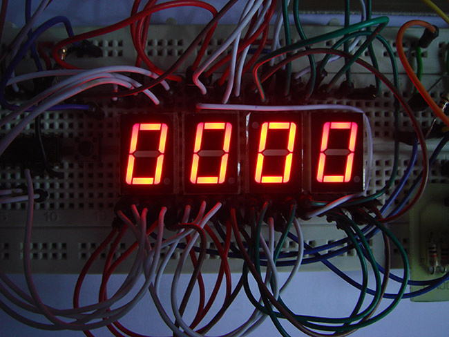
Image courtesy : Zx Lee Blog
Today we are about to see how to build a DIY stopwatch just using Digital IC’s 4026 and 4017. The most highlighting feature about this project is the fact that it doesn’t use any MCU to do the job. Even though using an MCU will be a lot better option still this project will be a great DIY for those who love to play with Digital chips.
BLOCKS OF DIY STOPWATCH:
- Oscillator
- Display
OSCILLATOR BLOCK:
Oscillator provides the clock source for stopwatch we are about to build. The oscillator should provide an output clock frequency of about 1Hz. There are plenty of ways to do this but each method might differ in accuracy of output wave produced. Even a simple 555 timer can be used here, but temperature drift might affect the accuracy of output. The deviation of output might not be that big but its good to have it under consideration.
Crystal powered oscillator will be the perfect solution for this problem. We are not going to discuss the oscillator section briefly in this article since this 1 Hz oscillator circuit will do a pretty good job for our DIY stopwatch project. You can always use other 1Hz clock generator circuits rather than the crystal oscillators provided your application have some tolerance on the accuracy.
DISPLAY BLOCK:
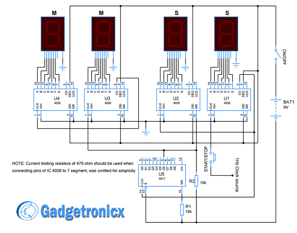 The display block uses 4 common cathode 7 segment for displaying the seconds and minutes of the count. The 7 segments marked as “S” for seconds and “M” for displaying minutes in the above circuit diagram. Use a 9v battery to power this block. Switch “ON/OFF” used to turn the counter ON or OFF. Use switch START/STOP to start and stop counting of Stopwatch.
Four IC 4026 (Decade counter with decoder which converts counter values to 7 segment outputs) was used to drive each of the 7 segment displays. The 1Hz clock from oscillator is fed into CLK pin of U1. With each incoming pulse in to the CLK pin of this IC ,the counter increments by one which in turn gets decoded and displays the value in 7 segment accordingly. When the count reaches the maximum value of 9 a high signal was sent out through the pin 5 CO of U1. This will the clock input to the next IC U2. So thus when U1 segment counts up to 9 CO signal will sent out to U2. Then it starts displaying the value 1 in its segment.
The segment associated with U2 will count up to 9 before returning to 0. But to stay withing the limit of 60 seconds we need to stop U2 before it hits 6 mark. So here comes along another IC 4017 (Johnson counter increments count values from Q0 to Q9 with each incoming input pulse) which is used to reset the IC U2 before it hits the 6 mark in its segment. To do so we have connected the Q6 pin to Reset pin (MR) of U2 and Reset pin of U5 itself. The clock from U1 was used by both U2 and U5 in order to keep the count similar for providing correct reset point. When the count in U2 and U5 reaches from 0 to 6 the Q6 pin in U5 goes high resetting itself and U2. Thus this sets the boundary of 60 seconds for our stopwatch.
The output from Q6 acts as clock source for the IC U3. So when 60 seconds count gets elapsed the minute segment associated with U3 increments to 1. When this U3 counts up to 9 the CO pin goes high which feeds clock to the chip U4. This is similar to the way U1 fed clock to U2. Then U4 starts counting from 1 with every clock input from CO of U3 and can count up to 9. Thus U3 and U4 segment combined can count up to 99. Therefore this DIY stopwatch has a count limitation of 99 minutes after it starts counting again from 0 minutes.
NOTE:
- Use current limiting resistors of 470 ohm should to connect the 7 segment pins from IC 4026. I have omitted it in the circuit diagram for simplicity.
- Use pull down resistors R1 and R2 to maintain pins at ground potential and prevent the chips from short.
- You can expand this stopwatch to display hours by adding two segments and 4026 more.
Hope you all will have fun building this stopwatch. Please comment below if you have any comments, suggestions and improvements with this project.


Hi
Which type of 7segment use in this common anode or common cathode segment
I implemented this circuit on Proteus Software but unfortunately, there are some logic problems that I can’t seem to understand. Can you help me in this regard?
1hz clock soucre ? That mean should connect to function generator?
It could be anything. The main idea is to have a clock source that gives a time period of 1 second for the timer.
Hi Frank
Nice circuit…and great website!
One question though, according to the datasheet, both ICs have pin 8 as ground. I noticed that you haven’t got either the 4016 or 4017 attached to ground through pin 8. Why is that?
Thanks.
John
Hi John,
I have left out the ground pins since the Circuit already looks complicated with lot of connections going around. Also Vcc pins are left out too.
Hi Sir
I´st possible to fix a resetbutton to this
DIY Stopwatch made out of Digital IC 4026 and 4017 ??
If, please send me a Circuit how to do it, Thanks
Hi Amnebrink,
It might make the design bit complicated. You can turn Off the circuit if you needs to reset, its simple as that
Hii..sir
i am having doubt that can we give 1Hz clock directly available on digital trainer kit?
Tanzeela,
Yes you can
Thanks sir