Obviously this isn’t the first siren circuit you come across in the internet. But most of the siren circuits in the internet does not actually produce the siren sound instead you will hear sounds such as “Tik- tok” or “Bim Bam” as output. The problem lies with the dual frequency square wave that drives the speaker like we see in most circuits. It’s is incapable of producing the variation and peak required for the Siren. The solution to this problem will be a Ramp or Triangle wave which will provide good variation in voltage and peak for your siren. So that’s the plan drive your speaker or buzzer using a Triangle waveform and you will get a good siren for yourself.
This siren circuit comprises of three separate blocks, they are
555 Astable multivibrator – Generate Square waves
OpAmp Integrator – Converting square to triangle wave
Opamp Non inverting amplifier – To amplify signal and drive buzzer
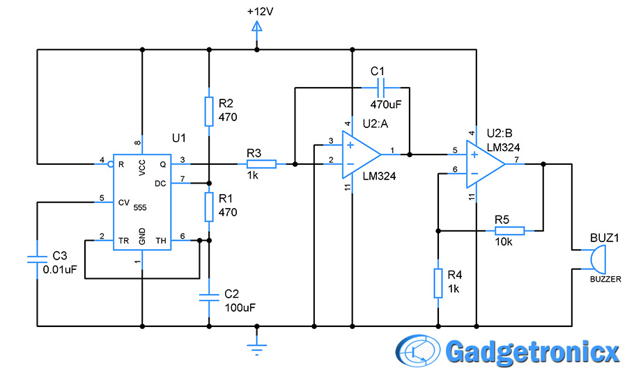
SIREN CIRCUIT DIAGRAM:
WORKING EXPLANATION OF SIREN CIRCUIT:
SQUARE WAVE GENERATION:
It’s all starts with the 555 chip which was wired as an astable multivibrator in the above circuit. The 555 along with R1,R2,C2 and C3 forms the astable multivibrator which in turn generator square wave as output of fixed frequency. The frequency of square waves can be fixed by the components R2,R1 and C2 in the circuit. The formula for deciding the output frequency was given by
Now our next objective is to convert the square wave pulses into triangle wave which is used to drive the buzzer. For that purpose LM324 a quad opamp IC was chosen and an integrator was constructed around first opamp U2:A. The integrator is a circuit which performs the mathematical function of integration to any input signal fed into it. In our case we are providing the opamp with square wave which after undergoing integration turns into a triangle wave. The working of this integrator converting the square to triangular wave is as follows.
When the square wave was fed into the inverting input of the integrator no current will be allowed into because of the virtual earth maintained at the pin 2 of U1:A. But the capacitor starts gradually charging through the current flowing into it. Initially the impedence of capacitor will very low and starts increasing proportional to the rate of charging in capacitor C1. The rate of C1 charge is given by the product of R3 and C1. At this point since the capacitor is connected from output pin 1 to (-) pin 2 the opamp is forced to produce linear voltage rise in negative direction as output to maintain the virtual earth.
This continues as long as the step input of square wave changes. This repeats but in opposite direction for the low state input of the incoming square wave. Thus with each high and low states of square waves we will get triangle pulse as output but in opposite direction. For positive high input we will negative ramp and negative ramp for low input. Thus output will be 180 degree out of phase with input.
AMPLIFYING OUTPUT:
Now we have successfully converted the square wave into triangular waveform. Now a problem arises, the output voltage will be low so that you will barely hear the siren sound from the buzzer. To rectify this we have used the third opamp as a non inverting amplifier. This requires two resistors R5 (feedback resistor) and R4 connected to U2:B as shown in the circuit diagram. The gain of this amplifier is controlled by the two resistors R5 and R4 and the formula is
Vgain = 1 + R5/R4
After amplification you will get a loud wailing real siren sound out of your buzzer or sounder. Now you got a loud siren for yourself, you can make this even better by using speaker as a sounding element provided you supply enough current to drive it.
NOTE:
You cold substitute R1 with a Pot to vary the frequency of the output wave obtained.
The feedback capacitor C1 value may subjected to change for precise adjustment of the siren sound, experimenting is better.
You can substitute a speaker in place of the buzzer for better sound but keep that in mind speaker requires more current to operate than buzzer, design accordingly.
Hi Ahsan,
The above circuit is tested and tried. You should not rely on simulator software 90% of time it fails to simulate, try this circuit in a breadboard and test the outcome

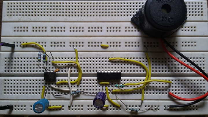


We build circuit,when we give 12V buzzer is running but how we can control sound using 555 timer.
i had made this circuit in proteus 8 but i am not getting enough output…… i am getting 0.49 volts which is not efficient for driving a buzzer…
Hi Ahsan,
The above circuit is tested and tried. You should not rely on simulator software 90% of time it fails to simulate, try this circuit in a breadboard and test the outcome