
Sensor modules are widely used in many digital as well as analog applications. The complexity level of a sensor varies largely and may be chosen based on the applications we are about to use it. Building a sensor module isn’t that difficult and we can do it by our own with simplest components. This article will take you to a walk through to build simple sensor modules by your own.
VOLTAGE DIVIDER:
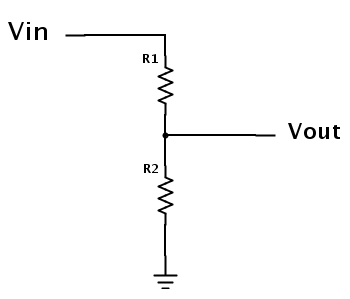
We all know that Voltage divider is one of the basic part of a circuit and we can find it in almost every electronic circuit. The above diagram shows the onstruction of a simple voltage divider where two resistors are hooked together and output is obtained in a point between these two resistors. These dividers are used to deliver the exact voltage we need to feed to a circuit. Our sensor modules also uses a similar concept since LDR, Thermistors and other sensing components have the capability of changing their resistance to the current flow according to their respective sensing parameter measure such as Temperature,light etc.
The Equation governing the Voltage output from a divider was given by the formula
Vout = Vin x R2 / (R1+R2)
LIGHT SENSOR MODULE CIRCUIT:
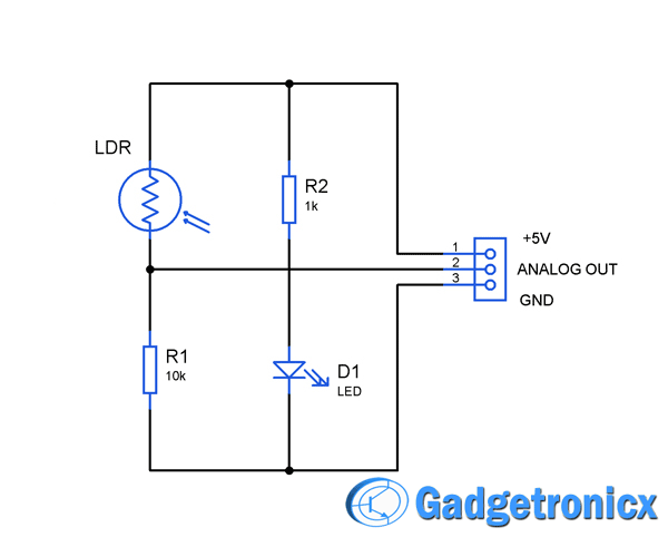
LDR (Light dependant Resistor) forms the base of this sensor module circuit. The LDR has the property of providing altered resistance for the current flow which depends on the incident light on it. Here the LDR is connected with resistor to form a voltage divider.
The Output voltage from the divider was connected to the Analog out pin from there the output was obtained. When there is no incident on the LDR it exhibits high resistance therefore the Analog out pin will be in low state.
When LDR is exposed to light the voltage level starts increasing based on the intensity of the incident light. When the intensity of the light is at maximum level the voltage output will be reach maximum. You can replace the R1 with a Pot to adjust the sensitivity of the sensor.These type of sensors are used in Analog applications where the output voltage is proportional to the incident light on it.
FOR DIGITAL APPLICATIONS:
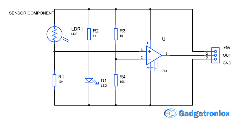 In case of digital circuits a simple modification will make it more efficient since digital circuits deal with high and low level voltages that is logic 1 and logic 0 and using analog output values may lead to false triggering of digital levels.
In order to avoid that a Op amp was used along with the analog one. Here the voltage output from the divider pair LDR and R1 was fed to the non inverting terminal of the Opamp. Another Voltage divider using the Resistor R3 and R4 was made and the output voltage of thaty divider pair should be fed into the inverting terminal of op amp. The choice of the R3 and R4 should be based on the desired voltage at which the op amp should be triggered.
NOTE:
- LDR can be replaced with thermistor in order to turn into a simple temperature sensor circuit.
- Microphone can be placed along with a series capacitor to turn the above into a sound sensor circuit.


