
The technique of controlling motor speed using PWM signals is very common. This circuit uses similar PWM technique to control motor speed and uses IC 555 to generate PWM signals. For those who are not aware, PWM or Pulse Width modulation , is a modulation technique in where the width of the output pulse varies with with respect to time. This therefore changes the duty cycle of the wave which in turn modifies on and off time of this PWM signal. Lets see how this DC motor speed control circuit works.
WORKING OF DC MOTOR SPEED CONTROL CIRCUIT:
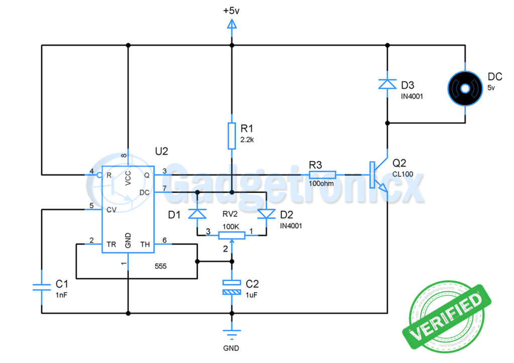
The heart of this circuit is an Astable multivibrator built out of IC 555. This multivibrator produces a series of square wave pulses as output of fixed frequency. Generally the output frequency of the Astable multivibrator depends on the Resistors and Capacitors attached to it.
A 555 astable multivibrator output duty cycle can never go down below 50%. In order to achieve PWM signal in output we should be able to modify the duty cycle as per our desire. This is where the components D2,D1, RV2 comes into picture.
Working of this astable multivibrator depends on the resistors and capacitor used with pin 7, pin 6 and pin 2. When the circuit is powered ON capacitor C1 charges via resistor R1 and RV2. But if you notice the circuit the current from R1 can pass through only one terminal of our variable resistor since D2 is reverse biased.
Hence D1 allows current to flow through it and RV2 exhibits some resistance to the current which depends on the position of the pot. When the capacitor is charging output of IC 555 will be in high state.
Once the capacitor charges up to 2/3 vcc, internal discharge transistor which connects to pin 7 goes high. Now output of IC 555 will goes to low. This forces the capacitor to discharge through RV2. But this time the discharging current goes through diode D2 since D1 is reverse biased.
The resistance exhibited by RV2 to discharging current will be different from what exhibited to charging current of capacitor. Therefore the discharge time of capacitor will be different from charging time.
This varied charging and discharging time will modify the width of our output pulse. This results in a PWM output signal in the output. When RV2 is set up in a way it exhibits very high resistance to charging current coming from D1, output pulse will have longer ON time.
On the other hand this will leave low resistance path for discharge current going out via D2, therefore Capacitor discharges quickly making the OFF time shorter. Thus we will get a high duty cycle PWM pulse. If we reverse the resistance, low time will longer and high time will be much shorter comparatively. This will allow us to get PWM signal much lower than 50%.
CALCULATION:
We can perform a simple calculation to understand this better.
Charging time or ON time = 0.693 ( R1 + RV1 ) C2
Discharge time or OFF time = 0.693 x RV2 x C2
If the variable resistor was set to exhibit 10k resistance between terminal 1 and 2. Then this will be the resistance to charging path by RV1. At this point terminal 2 and 3 in RV2 will exhibit 90k resistance to discharge path. Substituting the values in above formula
ON time = 0.693 ( 2.2k + 10k ) 1uF
= 8.5ms
OFF time = 0.693 x 90k x 1uF
= 62.37 ms
T = ON time + OFF time = 8.5ms + 62.37ms = 70.87ms
Duty cycle = 8.5ms / 70.87ms = 12%
Now if we alter the RV1 to make the resistance in terminal 1 and 2 as 90k and terminal 2 and 3 as 10k. Our duty cycle changes vastly
ON time = 0.693 ( 2.2k + 90k )1uF
= 63.9ms
OFF time = 0.693 x 10k x 1uF
= 6.93ms
T = 63.9ms + 6.93ms = 70.83ms
Duty cycle = 90%
From the above calculation you can see that providing different charging and discharging path with different resistance will enable us to produce PWM pulse from IC 555. Modifying the resistance value of RV1 between its terminals will modify the duty cycle.
MOTOR DRIVER:
The next stage of this circuit is quite. The output of the IC 555 is pretty low to drive a motor that can consume 500mA. Therefore a transistor is used as a switch here. The PWM signal is will drive the base of transistor Q1. This drives the motor according to the incoming signal from the output of the 555 IC. When the duty cycle of the PWM signal is high then the speed of the motor will be high and vice versa. Diode D3 is used to arrest the reverse current from motor when it is turned off.
PCB DESIGN:
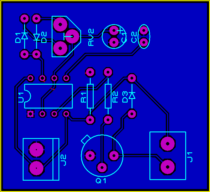 J1 the two pin screw terminal that connects DC motor to the circuit and J2 to connect power supply to the circuit. You can download the gerber files from below button.
VIDEO EXPLANATION:
This circuit is simple to implement and very efficient in working.This will be a great project to do for Electronics hobbyist and students. If you have any questions leave them in the comment box below.


What is use of C1 in Circuit ?
ciao.
posso usare un alimentatore 5V 500 mA per la parte dei 12V.
dovrò sostituire qualche componente…
i due – negativi…vanno sul piedino 1…a massa?
Grazie
Hello.
I can use a 5V 500 mA power supply for the 12V part.
I’ll have to replace some components …
the two – negatives … go on pin 1 … to ground?
Thank you
Giuseppe,
From my experience in most cases the motor will run even though it is powered by source which has less voltage than rated. But the speed will be very less and of course current consumption will be less
Hi
Is it a closed loop or open loop and why ?
Thank you
Franky,
It’s an open loop, because no feedbacks are in place.
Sir can u suggest the motor control video plzz
Can I use 9V instead of 12V to supply power to 555 timer IC ? Can i use 12V,2A dc power adapter for this purpose ?
Hello,
I just built this circuit, however I used a 100k POT as I don’t have a 50k. It seemed to be working fine, but the 33ohm begin to get hot and eventually smoked. I’m wondering why this happened, Lol. Using N4004 diodes as well.. 3VDC motor..
Hi Lyman,
That’s pretty strange! Can you tell me what is the max current rating of your motor under load and no load condition.
Student here, what is the voltage of the motor? Thanks..
Arnold,
Any voltage of your desire can be applied at +v terminal based on your motor rating. But make sure that your driving transistor Q1 can handle that voltage
We just made this circuit and it works beautifully!
https://youtu.be/KcqXn1VI-cs
Video posted on YouTube
RDoctorD,
Great, thanks for sharing 🙂