Disco lights Circuit have been quite famous among the lighting circuits made using LED’s. 555 timers are widely employed in lighting circuits like this to spice up the lighting effect produced by the circuit. Here we are about to see a similar lighting circuit using a timer IC 555 and a decade counter CD 4017. The IC CD4017 was a Johnson counter which gives decoded outputs with inputs of clock signal, clock inhibit, carry out and this it produces counters as output. Here is a similar Disco Lights Circuit which uses the same IC 555 and CD 4017. Lets move into the working explanation of this lighting circuit.
WORKING OF DISCO LIGHTS CIRCUIT:
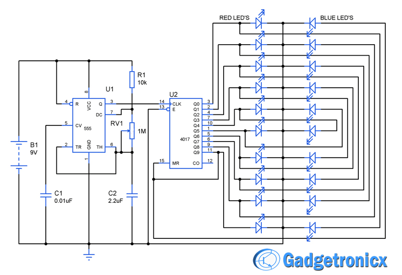
The Circuit operation starts with the IC 555 which is wired as a Astable Multivibrator to generate clock pulses for the counter IC CD4017. The frequency of the MUltivibrator decideds the speed with which the LED’s switch ON and OFF. The values of the variable resistor RV1, resistor R1 and Capacitor C2 decides the output timing of the Astable multivibrator.
CD4017 Pin diagram
Johnson COunter IC2 CD4017 forms the next part of the circuit. This IC takes clock input from the astable multivibrator through the pin 14. There are ten decoded ouput pins in this IC starting from Q0 to Q9. The output of the Johnson Counter increases one by one with each clock input signal and therefore the high signal moves from Q0 to Q9 pins with each pulse. The 13 Clock Enable pin should be given active low to give clock input to the IC. The reset 15th pin was used to reset the counter and when this pin goes high the Q0 output pin will be enabled for the continuation of next cycle.
Connection patterns of the LED’s play a very important role in this circuit , since wrong patterns may produce undesirable results. Two LED’s are connected to each ouput pins of the IC CD4017 and are connected in a manner two have a common cathode and two anodes. With the first clock pulse Q0 goes high while all other decoded outputs are low. This lights up the LED D1 in which the anode is positive with respect to the common cathode point. The high signal from the Q0 was also connected to the anode of the D11 which is also positive with respect to the common cathode. Therefore a high signal in Q0 pin will make the LED D1 and LED D11 glow.
This cycle continues as the high output moves to Q1 for next clock pulse input from the multivibrator. This makes the LED D2 and D12 to glow at the same moment. And the cycle continues with high output proceeds to Q3, Q4, ……..Q9 making the LED’s D3 & D13, D4 & D14, ……..D10 &D20 to glow in pairs. This will produce a great lighting pattern similar to disco lights and remember adding different color LED’s will make this Lighting circuit even cooler.
I have also added the Proteus simulation file along with this article , Download the design file from below link to get a better idea of its working.
I cannot access the simulation file… The system gives me an error and i really need t take a look at it to help me with my project.
Please can i get it send to this email youngbrainax6000@gmail.com
Thank you.
Sailesh,
The power pin was not displayed in the schematic, it should be understood by the reader when trying out this design. This makes the design looks less complex.
Well… You did put the power pins on the 555, why not on the 4017?
One thing that is true, though, is the schema appears fairly complicated, while the end circuit is actually pretty simple once you have figured out how to wire the 4017 (what a mess of wires crossing everywhere!), same for the 555. And the GND pin is fairly important in many applications of the 4017, as it’s pretty much the only way of controlling if the current flows in each of the pins (one transistor to rule them all).
Regis,
Its all depends upon the design software we use. You cannot wire a power and ground pins if there is none at all. In case of 555 the pins are there so connected them. In short, it should be understandable by the reader.
Nikita,
The frequency for a astable multivibrator was given by the formula f= 1.44/((R1+RV1*2)*C2) …If you have a specific frequency in mind then you can substitute that value in above formula and solve for the value of resistor or capacitor by fixing either one of these parameters. You can calculate resistor value by using these formulas R1= 1.44**(2*D-1)/(F*C2) and R2(RV1)= 1.44*(1-D)/(F*C2) but in this case also you need to fix D- Duty cycle and C2 – capacitance values.


I cannot access the simulation file… The system gives me an error and i really need t take a look at it to help me with my project.
Please can i get it send to this email
youngbrainax6000@gmail.com
Thank you.
Hi Divine,
You should be able to download the file now. Please note that it is Proteus design file. Hope it helps
Good
Its amazing how that 4017 works without power
Sailesh,
The power pin was not displayed in the schematic, it should be understood by the reader when trying out this design. This makes the design looks less complex.
Well… You did put the power pins on the 555, why not on the 4017?
One thing that is true, though, is the schema appears fairly complicated, while the end circuit is actually pretty simple once you have figured out how to wire the 4017 (what a mess of wires crossing everywhere!), same for the 555. And the GND pin is fairly important in many applications of the 4017, as it’s pretty much the only way of controlling if the current flows in each of the pins (one transistor to rule them all).
Regis,
Its all depends upon the design software we use. You cannot wire a power and ground pins if there is none at all. In case of 555 the pins are there so connected them. In short, it should be understandable by the reader.
sir, i wanted to know how to calculate resistor & capacitor values for above ckt..(dancing bicolor led’s)
Nikita,
The frequency for a astable multivibrator was given by the formula f= 1.44/((R1+RV1*2)*C2) …If you have a specific frequency in mind then you can substitute that value in above formula and solve for the value of resistor or capacitor by fixing either one of these parameters. You can calculate resistor value by using these formulas R1= 1.44**(2*D-1)/(F*C2) and R2(RV1)= 1.44*(1-D)/(F*C2) but in this case also you need to fix D- Duty cycle and C2 – capacitance values.
thank you sir….
i want to design a led circuit so plz suggest subject…
Nikita,
What sort of LED Circuit? Specify please!