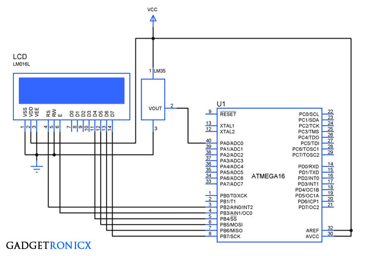
ADC holds an important significance in every Microcontroller since it allows user to measure the external analog parameters and gives the result in digital form. Almost every advanced Microcontroller is equipped with ADC and so does ARM series controllers. This tutorial is all about ADC programming in ARM microcontrollers and interfacing of temperature sensor LM35 with it.
ADC IN ARM MICROCONTROLLER:
ARM controllers consists of a 10 bit Successive approximation ADC with 4 to 8 pins based on the Controller. This ADC operates from 0 to 3V so the input voltage from the sensor should not exceed 3V.
REGISTERS USED:
ADCR:
A/D control register which was used yo select the operating mode in which the ADC should operate. SEL bits in this register used to select the channels we are about to use. CLKDIV bits are used to produce the clock for A/D converter which should be less than 4.5MHz. PDN bit is to choose the operational mode while START bits are used to start the A/D conversion.
ADDR:
A/D Data register is a 32 bit register which consists of the result obtained from the A/D conversion along with the Flag bit which indicates that the conversion is complete. It do also consists of several other registers each of them serves a specific purpose. The 6-15 bits of this register holds the converted values which can be retrieved by shifting the values.
I have given a simple description of the registers we are about to use. However for deep understanding kindly refer to the Manual which provides a brief explanation of the bits in these registers. Download the manual from the below link
CALIBRATION:
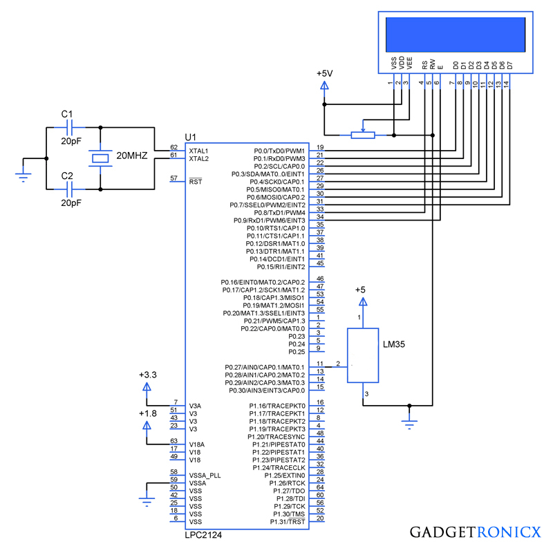
For the illustration of ADC working we are using a simple temperature sensor LM35 in which the output voltage changes by 10mV with rise or fall in each degree temperature. And it can sense temperature up to 150 degree Celsius. In ADC’s we always must perform calibration to obtain real value. Since we are using a 10 bit ADC our resolution will be 2^ 10 =1024
Step Size = Reference voltage / Resolution = 3.3v / 1024 = 3.22 mV
So the value of the ADC changes with change in Ain voltage of about 3.22mV. The temperature sensor gives 10mV change in output with every change in temperature. For a degree change in temperature A/D value will undergo 3 increments 3.22mV * 3 = 9.7mV which is approximately equal to 10 mV. So we have to divide the A/D value by 3 to obtain the real time temperature.
CODE:
This code was built using Keil uVision 4 IDE.
#include<lpc21xx.h>
#include<stdio.h>
unsigned int temperature;
int i;
char conv_temp[8];
void adc(void);
void lcd(unsigned char data,int rs_status);  //lcd subroutine
void delay(void);

int main(void)
  {
   PINSEL0=0;
   IODIR0=0x00000fff;
   VPBDIV=0x00;
   PINSEL1=(1<<22);                  //Specifying A/D pin function
   lcd(0x38,0);                            //lcd intialization
   lcd(0x0c,0);
   while(1)
      {
lcd(0x80,0);
adc();
         }
   }

void adc(void)
   {
     ADCR|=(1<<0)|(1<<16)|(1<<8)|(1<<21)|(1<<24); //mode selection
       while(!(ADDR&(0x80000000)));         //Checking conversion status
       temperature=(ADDR>>6)&0x3ff;     //Reading A/D value
     temperature=temperature/3;          //Real temp conversion
       sprintf(conv_temp,"%lu",temperature);   //int to char conversion
       for(i=0;i<=5;i++)
       lcd(conv_temp[i],1);
   }

void lcd(unsigned char data,int rs_status)
   {
     IOSET0=(data<<0);
       IOSET0=(rs_status<<8);
     IOSET0=(1<<9);
       delay();
       IOCLR0=(1<<9);
     IOCLR0=(rs_status<<8);
       IOCLR0=(data<<0);
   }

void delay(void)
  {
     unsigned int j;
     for(j=0;j<=10000;j++);
  }


Dear,Frank Donald thank you for your post.
I worked in this program and i simulated it,i observed some error in calibration of ADC ,but it’s very useful and your explanation is very good , i suggest you to please keep the ADC registers snippets.I changed your code as **temperature/3 to **temperature/3.1 it works fine.
Nikhil,
Glad you find it useful. Yeah calibration errors might occur because of the decimal values in the calculation. But it can be corrected with few tweaks in the code just like you did. I will take your suggestion thanks 🙂