7 Segments are commonly used display devices which is capable of displaying numbers from 0 o 9 and some alphabets. It is more common in Embedded applications where we need to display some numerical values. This tutorial will cover the interfacing of 7 segment interfacing with 8051 microcontroller and how to program it to display numerical or characters.
TYPES OF 7 SEGMENT:
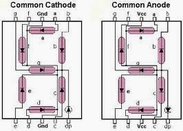 |
| Common anode and Common cathode Display |
We know LEDs are inside a 7 segment display but there are different ways it will be connected inside a 7 segment. Based on LED connection there are two types of 7 segment, one is Common Cathode and other one is Common Anode. Both of them vary with their mode of connections and programming. As we all know that 7 segment is made of series of LED’s aligned together to perform the function of display.
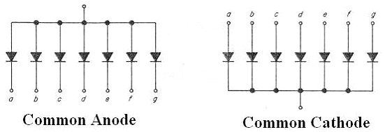 |
| Connection configuration of 7 segments |
There is one common difference between these two segments, that is they both differ in how the LED’s are sourced in it. Common Anode segments draw current directly from the power source and sink it to Microcontroller pins. But Common Cathode LED’s are sourced by Microcontroller pins and sink the current to GND. If you look at the above diagram the alphabets a,b,c,d,e,f,g indicates the 7 segment pins which connects with microcontroller. Noticed the difference between both of them.
DISPLAYING NUMERICALS OR CHARACTERS IN 7 SEGMENT:
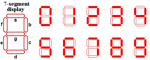 |
| Digit formation in 7 Segment |
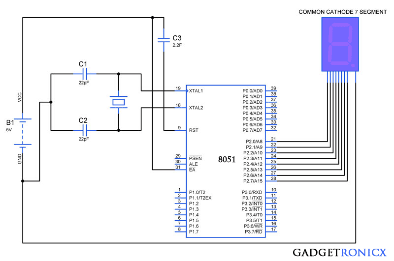
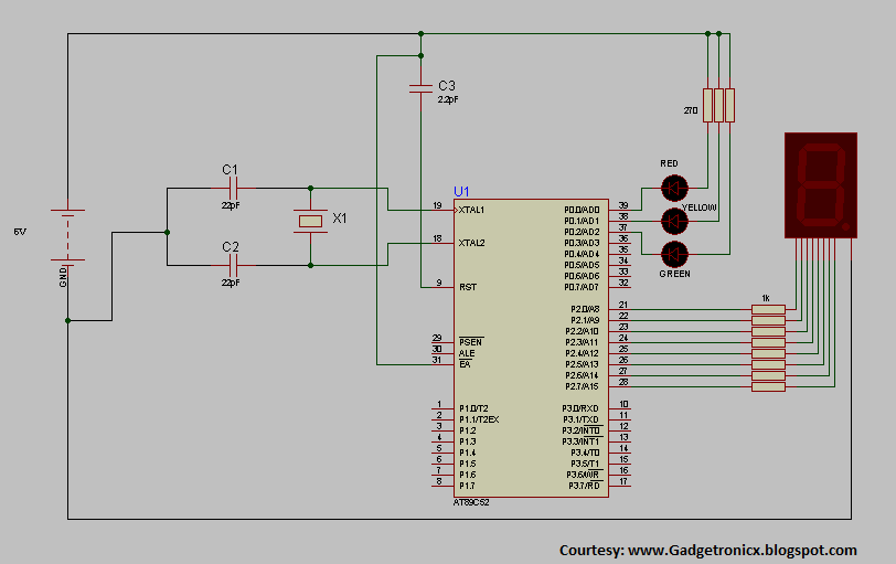
In 7 segment the display of digits is done by means of turning on or turning off the LED’s within them. For example if we need to display the digit ‘0’ we need to enable LED’s “a,b,c,d,e,f” , that is applying logic 1 or sourcing from microcontroller in case of Common cathode and applying logic 0 or sinking through pins in case of common anode. So after connecting 7 segment from P2.0 to a ………P2.7 to dp of 7 segment below are some of the hex codes to display respective numbers
0 – 0011 1111 – 0x3F
1 – 0000 0110 – 0x06
2 – 0101 1011 – 0x5B
Similar to this we can program to display any digits of our desire by feeding hex code to the ports of the Microcontroller.
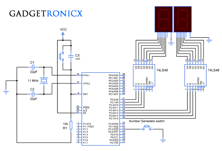
CONNECTION DIAGRAM:
CODE:
The below code will display 0 to 9 digits in the 7 segment with some specific time intervals between each count.
#include<stdio.h>
#include<reg51.h>
void delay(void);
unsigned char array[10]={0x3f,0x06,0x5b,0x4f,0x66,0x6d,0x7d,0x07,0x7f,0x6f}; //Hex values to display digits 0 to 9
void main()                       //Main Program
  {
   while(1)
    {
      unsigned int i;
      for(i=0;i<=10;i++)
       {
        P2=array[i];             //Sending hex values one by one
        delay();
       }
    }
  }
void delay(void)              //Delay Function
  {
    unsigned int s,k;
    for(s=0;s<400;s++)
     {
      for(k=0;k<200;k++);
     }
 }
For 7 Segment common anode displays you need to give logic 0 to the LED segments in order to light up.
NOTE:
- Modify the line 12 in the above program as P2=~array[i]; to make it work for common anode segment.
- “~” sign will complement all the values to apply logic 0 at desired pins of the 7 segment.

sir in this ur wring loop for(i=0;i<=10;i++)
here we r using 0 to 9 its mean total 10
from ur code accepts 11 numbers 7 segment accepts only 0 to 9 in this segment cant shows 10
sir plz code modification loop for(i=0;i<10;i++) or for(i=0;i<=9;i++)