FM transmitters have been used all over the world for communication. The simplicity of building a FM circuit made it so popular among other modulation techniques. Today i have come up with FM transmitter circuit which has a range of about 3 Km approximately. The circuit diagram was pretty wide and i cannot fit it into this webpage. Click on it to see large resolution image. Let’s get into the working part of this circuit.
WORKING OF FM TRANSMITTER:
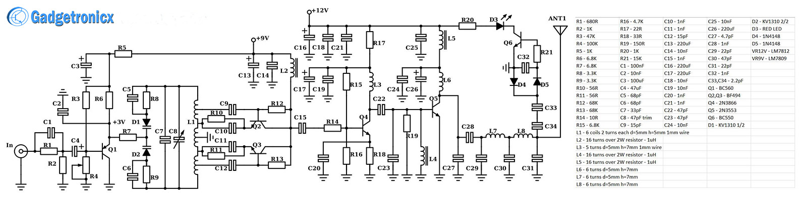
There was a lot of components and parts in this circuit so i will keep the explanation simple as possible. This is a good quality FM transmitter with a stable frequency brought by the modified oscillator, which is actually two oscillators built around Q2 and Q3 working at around 50MHz in anti-phase. The output is taken at the two collectors, where the frequencies of the two oscillators combine to form a 100MHz signal. This will provide a greater stability than normal single ended oscillators.
The modulation is done via the dual varicap D1/D2 and the variable capacitor C8. By changing the reverse bias voltage on the varicap (according to an input signal) you essentially change their capacitance thus the resonance frequency of the tank circuit. This leads to frequency modulation of the input signal virtually. The output of the oscillator/modulator stage is fed to a class A driver stage built using the transistor Q4. The output signal is further strengthened by feeding in to a class C power amplifier built around Q5.
Now feed the output signal from Class C to low pass filters made of series of Capacitors and Inductors. This is done to achieve lowest harmonics spurs at the output before feeding it to the antenna. I have added an indicator LED D3 which shows that you’re transmitting and everything is working fine. If the LED doesn’t light up then something is wrong with the schematic. The problem usually occurs in the oscillator part (just for a hint). Also I managed to remove almost all variable capacitors but the one for the tuning, because the original schematic had a lot more variable capacitors and it’s hard to tweak them all.
RANGE OF FM CIRCUIT:
The power of output signal in this FM circuit is 2.5W . At 2.5W FM signal is capable of covering 5 – 7 Km distance with good line of sight. And in best case scenario it might even reach 10km approximately. So i believe it will be fair to say that this circuit will cover 3 Km range even under semi optimum or worst external conditions.
This circuit was designed for European FM receiver systems although it’ll work in America as well, I’m not really sure if the audio quality will stay the same. That comes from the fact that I’ve used a 50us preemphasis which is the European standard and USA works with 75us preemphasis.
PCB TIPS:
When building this circuit, there are few PCB considerations which you have to follow. It’s very important to use a ground plane instead of a ground rail when wiring the system. This increases the ground area and stability. You can also build a balun just before the antenna feed line by coaxing 3 or 4 turns of the coaxial cable with a length of 21 inches. As a result this will create a resonant trap for electrical fields flowing on the cable’s outer shell, and prevent making it to part of the antenna, which is undesirable.
NOTE:
Never start the transmitter without a load.
If you haven’t connected the antenna just put a dummy load resistor of 50ohm at 2W (carbon, not wire wound) and test your circuit.
I hope you all will like this project, do try this and post your outcome. For queries please use the comment box below, I will be happy to answer it. Happy DIY making 🙂
Tanks for this long rang fm transmitter pls i need a little explanation on the following
L1-6coils 2turns d=5mm,h=5mm ,1mm wire
L2 ,L4 and L5 ,16 turns over 2Watt resistor 1uH
L3,L6,L7 and L8 :6turns d=5mm,h=7mm


 RF Remote control circuit")


Tanks for this long rang fm transmitter pls i need a little explanation on the following
L1-6coils 2turns d=5mm,h=5mm ,1mm wire
L2 ,L4 and L5 ,16 turns over 2Watt resistor 1uH
L3,L6,L7 and L8 :6turns d=5mm,h=7mm
pls explain to understand
thanks
it means 1mm coil should be wound on 5=mm and 5mm height
Please leave a crystal FM transmitter.
Here we have learnt some unique information about FM circuit. thanks for sharing this useful information