Circuit designing can be pretty daunting since the things in reality will be far different from what we read in books. It’s pretty obvious that if you need to be good at circuit design you need to understand each components and practice quite a lot. Apart from this generic saying here is a list of ten tips that can help you to design better circuits, of course these are not the only tips out there but it’s a start. Let’s get into the tips.
DESIGN TIPS IN A VIDEO:
I have made a video to explain these tips, if you are looking for a quick and short route to get familiar with the tips, I suggest you to watch the video 🙂
1) USING DECOUPLING AND COUPLING CAPACITORS:
Capacitor are widely known for its timing properties, however filtering is another important property of this component that has been used by circuit designers.
DECOUPLING AND COUPLING CAPACITORS:
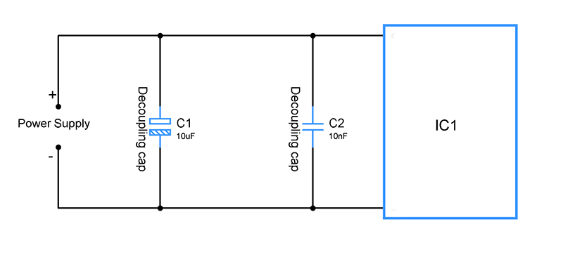
Power supplies are really unstable, you should always keep that in your mind. Every power supply when comes to practical life will not be stable and often the output voltage obtained will be fluctuating at least few hundred mill volts. We often cannot allow this kind of voltage fluctuations while powering our circuit. Because voltage fluctuations may make the circuit to misbehave and especially when comes to microcontroller boards there is even a risk of MCU skipping a instruction which can result in devastating results.
In order to overcome this designers will add a capacitor in parallel and close to the power supply while designing circuit. If you know how capacitor works you will know, by doing this capacitor will start charging from the power supply until it reaches the level of VCC. Once the Vcc level is reached current will no more pass through the cap and stops charging. The capacitor will hold this charge until there is a drop in voltage from the power supply. When voltage from the supply, voltage across the plates of a capacitor will not change instantaneously. At this instant Capacitor will immediately compensate for the voltage drop from the supply by providing current from itself.
Similarly when the voltage fluctuates otherwise creating a voltage spike in the output. Capacitor will start to charge with respect to the spike and then discharge while keeping the voltage across it steady thereby the spike will not reach the digital chip thus ensures steady working.
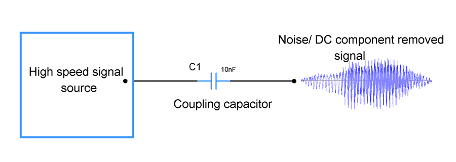
These are capacitors that are widely used in amplifier circuits. Unlike the decoupling capacitors will be in the way of an incoming signal. Likewise the role of these capacitors are quite the opposite from the decoupling ones in a circuit. Coupling capacitors block out the low frequency noise or DC element in a signal. This is based on the fact that DC current cannot pass through a capacitor.
The decoupling capacitor is extremely used in Amplifiers since it will curb the DC or low frequency noise in the signal and allowing only high frequency usable signal through it. Although the frequency range of curbing the signal depends on the value of capacitor since reactance of a capacitor varies for different frequency ranges. You may to pick the capacitor that suit your needs.
Higher the frequency you need to allow through your capacitor lower the capacitance value of your Capacitor should be. For example in order to allow a 100Hz signal your capacitor value should be somewhere around 10uF, however for allowing 10Khz signal 10nF will do the job. Again this is just a rough estimate of cap values and you need to calculate the reactance for your frequency signal using the formula 1 / ( 2* Pi * f * c ) and choose the capacitor which offers least reactance to your desired signal.
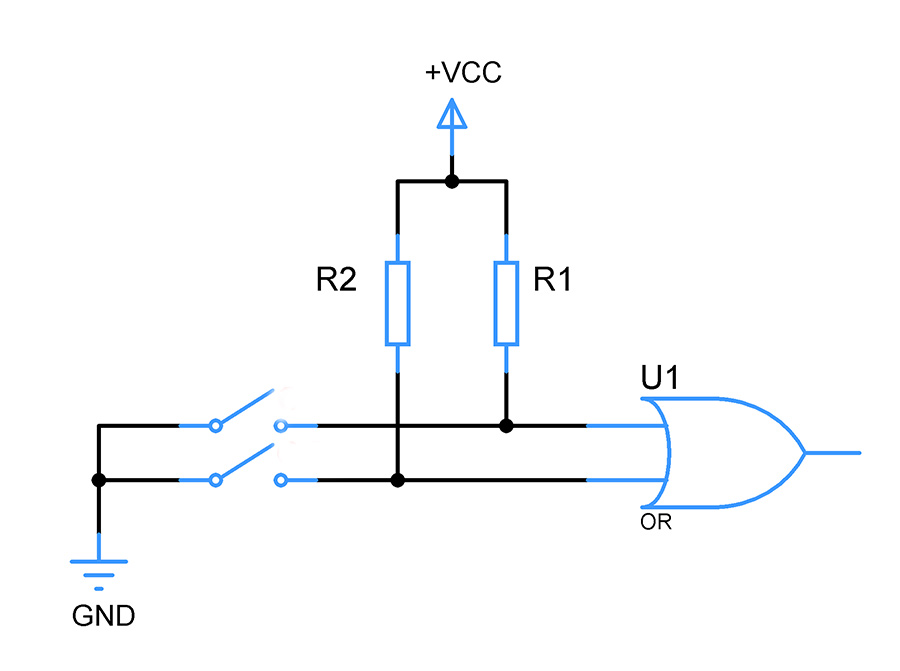
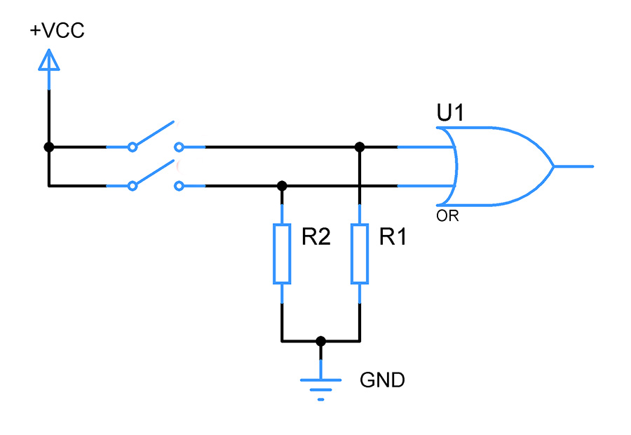
“Floating state should be always avoided” , we often hear this when designing digital circuits. And it is a golden rule you must follow when designing something that involves digital IC’s and switches. All the digital IC’s operates on a certain logic level and there are many logic families. Out of these TTL and CMOS are pretty much widely known.
These logic levels determines the input voltage in a digital IC to interpret it either as a 1 or a 0. For example with +5V as Vcc voltage level of 5 to 2.8v will be interpreted as Logic 1 and 0 to 0.8v will be interpreted as Logic 0. Anything that falls within this voltage range of 0.9 to 2.7v will be an indeterminate region and the chip will interpret either as a 0 or as a 1 we can’t really tell.
To avoid the above scenario, we use resistors to fix the voltage in the input pins. Pull up resistors to fix the voltage close to Vcc ( voltage drop exists due to current flow ) and Pull down resistors to pull the voltage close to GND pins. This way the floating state in the inputs can be avoided, thus avoid our digital IC’s from behaving incorrectly.
As I said these pull up and pull down resistors will come in handy for Microcontrollers and Digital chips, But do note that many modern MCU’s are equipped with internal Pull up and Pull down resistors which can be activated using the code. So you might check the datasheet for this and choose to either use or eliminate pull up / down resistors accordingly.
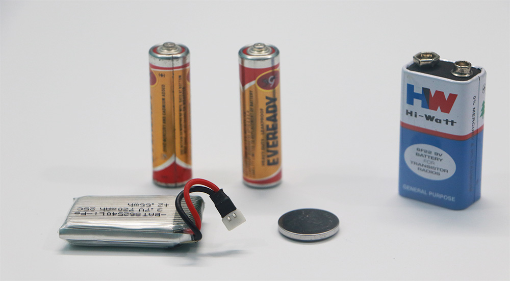
Batteries are a great source to power up your circuit. You will have to choose the battery if you want your design to be mobile. But choosing the right battery might be bit tricky than you actually think. That is because batteries are susceptible to drop their output voltage when their current capacity decreases. Although how far the voltage will drop depends on the type of battery you use ( Lithium ion, Lead acid, Alkaline batteries etc ), there is one good rule of thumb you should always remember.
Always use the battery that has 1.5 times capacity of the current you actually need to run your circuit for a given period of time. Let’s consider that I need to run a 12v motor along with its driver circuit for about 4 hours. The motor itself consumes 150mA and 50mA by driver circuit. So on the whole the entire block consumes 200mA. If I need to run the above circuit for about 4 hours then current required should be
200mA x 4 = 800mA
For this case you should be choosing a battery capacity of 1.2Ah. This is because Lithium ion batteries tend to drop their voltages when the current capacity drops to 20% of their total capacity. This means voltage will drop from 12v to somewhere around 9v when the current capacity drops to 240mA in Lithium battery. Here our circuit consumes 800mA for four hours as denoted above which leaves 400mA or 27% current capacity in the battery. Considering the losses this wiggle room should keep our circuit up and running and prevent damage of batteries as well.
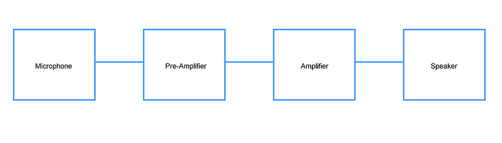
Circuit designing by itself can be pretty daunting but its is something very similar to building a house. Take any circuit you could probably find two or three building blocks in it which are put together to function as unit to perform the intended task.
Here is few of these individual circuit blocks – Voltage dividers, RC elements, RLC elements, Amplifier, multivibrators, Switches, Darlington transistor arrays, rectifiers, regulators, counters, registers, multiplexers.
To design circuits you need to have understanding on these basic building blocks on how it works and methods to build them. Once you possess fair knowledge on these blocks you will find yourself in a good position to design circuits for the intended purposes. But remember putting these elements together may not be straightforward and take practice to do so but this will give you a head start in making your circuit design.
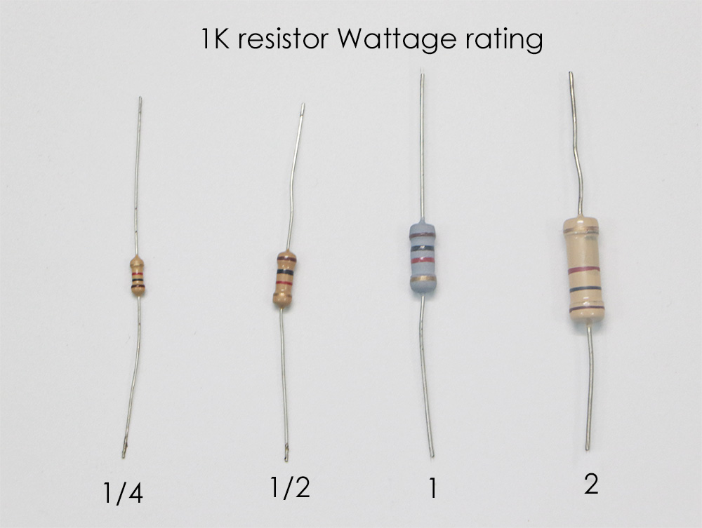
5) RESISTOR WATTAGE:
This is the thing which is commonly ignored by many novice designers and it is very important to take this into consideration when designing your circuits. Resistors as we know resist current flow through it at a given voltage. When this happens electrical energy will experience a loss in the form of heat.
Wattage rating or power rating of a resistor indicate the amount of power it can safely dissipate in the form of heat. When power dissipated exceeds the rated wattage it will result in smoking of resistor and potentially can damage the entire circuit. So Wattage rating of a resistor is equally important as their resistance values.
Let’s say you want to use a resistor in a circuit where it allows 100mA of current at 9V, so the total power here will be P=VI or P = 50mA * 9V = 0.45Watts. In this case we should choose a resistor with wattage rating of at least ½ or 0.5 Watt resistor.